1-18
CELL-DYN
®
3200 System Operator’s Manual
9140181K—July 2002
Use or Function
System Components
Section 1
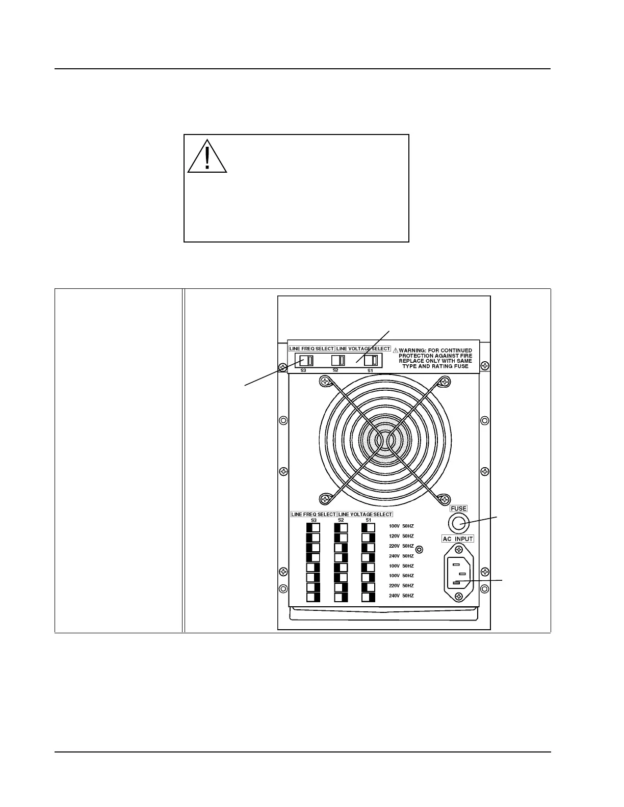
Line Frequency and Line Voltage Select Switches
These switches are used to select the Line Frequency and Voltage for the Analyzer
(refer to Figure 1.9).
WARNING: These switches are set at the factory for 120 volts. When operation at
other line voltage is required, refer to Figure 1.9.
Figure 1.9 Power Supply Module
Main Power Connector
This receptacle is used to connect the main power cord to the instrument.
Fuse
An 8-amp (110/120 V) T (Slo-Blo) or 4-amp (220/240 V) T (Slo-Blo) Fuse
protects the Analyzer from electrical spikes.
WARNING: SET FOR 120 VOLTS
When operation at other line voltage is required,
refer to Operator’s Manual for detailed instructions.
PN 9230003E
1 Line Voltage Select
Switch
2 Line Frequency Select
Switch
3 Main Power
Connector
4Fuse
3
2
1
4