96
ABOV Semiconductor Co., Ltd.
11.5 Timer 0
11.5.1 Overview
The 8-bit timer 0 consists of multiplexer, timer 0 counter register, timer 0 data register, timer 0 capture data register and
timer 0 control register (T0CNT, T0DR, T0CDR, T0CR).
It has two operating modes:
− 8-bit timer/counter mode
− 8-bit capture mode
The timer/counter 0 can be clocked by an internal. The clock source is selected by clock selection logic which is
controlled by the clock selection bits (T0CK[2:0]).
− TIMER 0 clock source: f
X
/2, 4, 8, 32, 128, 512, 2048
In the capture mode, by EINT10, the data is captured into input capture data register (T0CDR). In timer/counter mode,
whenever counter value is equal to T0DR, a match signal is generated.
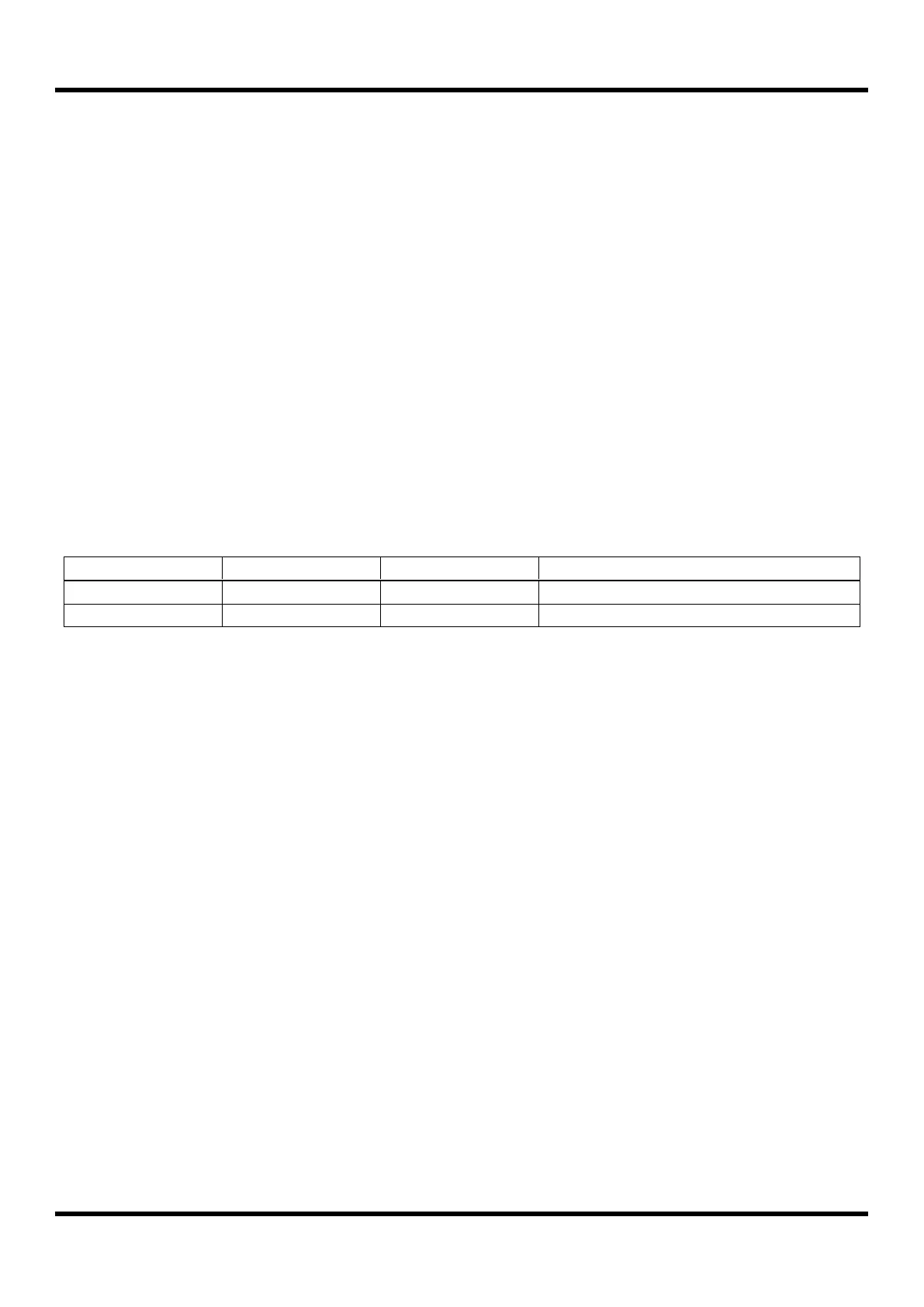
Table 11.5 Timer 0 Operating Modes

 Loading...


