97
ABOV Semiconductor Co., Ltd.
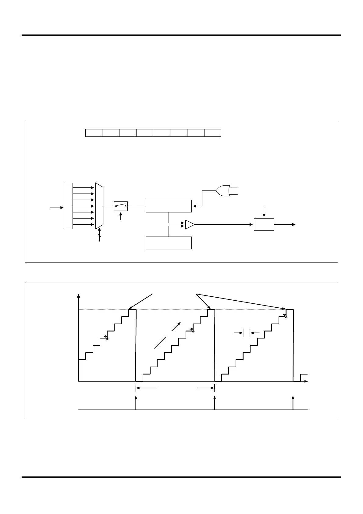
11.5.2 8-bit Timer/Counter Mode
The 8-bit timer/counter mode is selected by control register as shown in Figure 11.5.
The 8-bit timer have counter and data register. The counter register is increased by internal. Timer 0 can use the input
clock with one of 2, 4, 8, 32, 128, 512 and 2048 prescaler division rates (T0CK[2:0]). When the value of T0CNT and
T0DR is identical in timer 0, a match signal is generated and the interrupt of Timer 0 occurs. T0CNT value is
automatically cleared by match signal. It can be also cleared by software (T0CC).
P
r
e
s
c
a
l
e
r
fx
M
U
X
fx/2
T0CNT(8Bit)
fx/4
fx/8
fx/32
fx/128
fx/512
fx/2048
3
T0CK[2:0]
T0EN
8-bit Timer 0 Counter
T0DR(8Bit)
Comparator
T0IFR
8-bit Timer 0 Data Register
INT_ACK
Clear
Match signal
Clear
Match
To interrupt
block
T0EN - T0MS - T0CK2 T0CK1 T0CK0 T0CCT0CR
1 - 0 - x x x x
ADDRESS : B2H
INITIAL VALUE: 0000_0000B
T0CC
Figure 11.6 8-bit Timer/Counter Mode for Timer 0
Figure 11.7 8-bit Timer/Counter 0 Example
Timer 0
(T0IFR)
Interrupt
Interrupt Period
= P
CP
x (n+1)
 Loading...


