98
ABOV Semiconductor Co., Ltd.
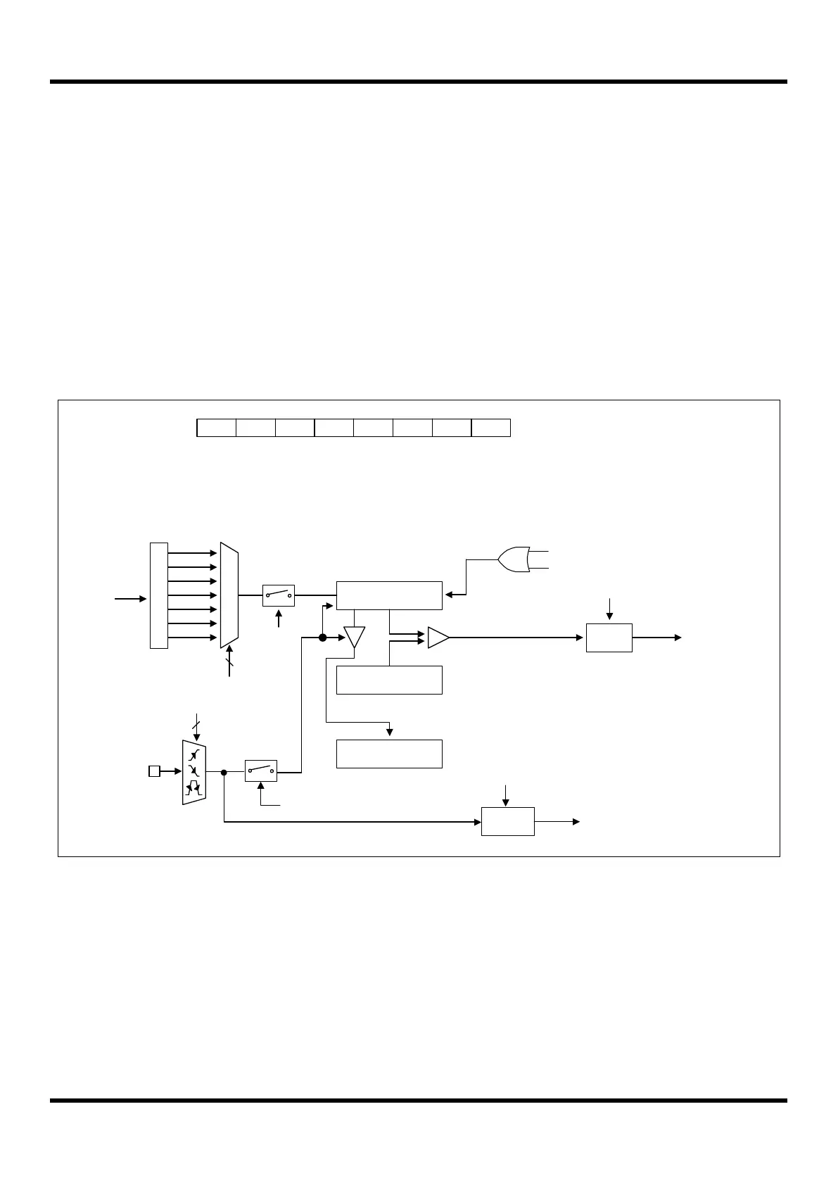
11.5.3 8-bit Capture Mode
The timer 0 capture mode is set by T0MS as ‘1’. The clock source can use the internal/external clock. Basically, it has
the same function as the 8-bit timer/counter mode and the interrupt occurs when T0CNT is equal to T0DR. T0CNT
value is automatically cleared by match signal and it can be also cleared by software (T0CC).
This timer interrupt in capture mode is very useful when the pulse width of captured signal is wider than the maximum
period of timer.
The capture result is loaded into T0CDR.
According to EIPOL1 registers setting, the external interrupt EINT10 function is chosen. Of course, the EINT10 pin
must be set to an input port.
T0CDR and T0DR are in the same address. In the capture mode, reading operation reads T0CDR, not T0DR and
writing operation will update T0DR.
P
r
e
s
c
a
l
e
r
fx
M
U
X
fx/2
T0CNT(8Bit)
fx/4
fx/8
fx/32
fx/128
fx/512
fx/2048
3
T0CK[2:0]
T0EN
8-bit Timer 0 Counter
T0DR(8Bit)
Comparator
T0IFR
8-bit Timer 0 Data Register
INT_ACK
Clear
Match
T0CDR(8Bit)
Clear
FLAG10
(EIFLAG1.4)
T0MS
INT_ACK
Clear
To interrupt
block
To interrupt
block
T0EN - T0MS - T0CK2 T0CK1 T0CK0 T0CCT0CR
1 - 1 - x x x x
ADDRESS : B2H
INITIAL VALUE: 0000_0000B
Clear
EINT10
EIPOL1[1:0]
2
Match signal
T0CC
Figure 11.8 8-bit Capture Mode for Timer 0
 Loading...


