135
ABOV Semiconductor Co., Ltd.
11.8.13 Register Map
USART Baud Rate Generation Register
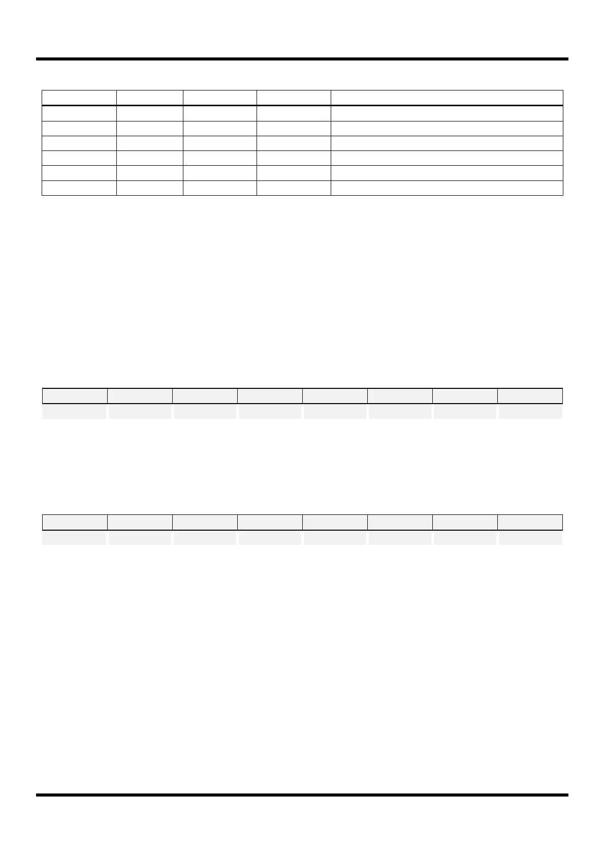
Table 11.12 USART Register Map
11.8.14 USART Register Description
USART module consists of USART baud rate generation register (USTBD), USART data register (USTDR), USART
control register 1 (USTCR1), USART control register 2 (USTCR2), USART control register 3 (USTCR3), and USART
status register (USTST).
11.8.15 Register Description for USART
USTBD (USART Baud Rate Generation Register) : DDH
Initial value : FFH
The value in this register is used to generate internal baud rate in UART mode or to
generate SCK clock in SPI mode. To prevent malfunction, do not write ‘0’ in UART
mode and do not write ‘0’ or ‘1’ in synchronous or SPI mode.
USTDR (USART Data Register) : DEH
Initial value : 00H
The USART Transmit buffer and Receive buffer share the same I/O address with this
DATA register. The Transmit Data Buffer is the destination for data written to the
USTDR register. Reading the USTDR register returns the contents of the Receive
Buffer. Write to this register only when the DRE flag is set. In SPI master mode, the
SCK clock is generated when data are written to this register.

 Loading...


