R3131 Spectrum Analyzer Operation Manual
2.3.3 Measuring Adjacent Channel Leakage Power (ACP)
ADVANTEST R3131
Thu 25 Jun 1998ACP
REF 0.0 dBm ATT 10dB A_wrt
10d8/ Posi Norm ACP
a Marker ON /OFF
CH BW 0 kHz
300 kHz 0.00 dB Channel
CENTER 1.895150 GHz
*RBW 10 kHz VBW 10 kHz
Spacing 1
— _
Channel
Spacing 2
ON /OFF
Channel
Band WD
Graph
ON /OFF
SPAN 2.00 MHz
SNP 50 ms
Figure 2-64 Displaying a Graph as a Result of Operation
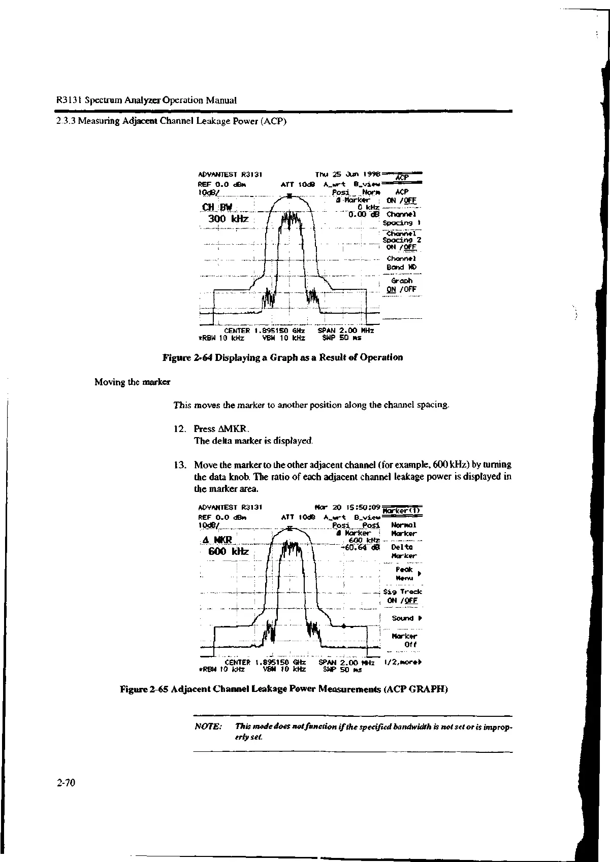
Moving the marker
This moves the marker to another position along the channel spacing.
12. Press AMKR.
The delta marker is displayed.
13. Move the marker to the other adjacent channel (for example, 600 kHz) by turning
the data knob. The ratio of each adjacent channel leakage power is displayed in
the marker area.
ADVANTEST R3131
REF 0.0 dBm
10d8/
WR
600 kHz
Mar 20 15.5009marker(1)
ATT 10dB A_wrt B_view
Posi Posi
Marker
600 kHz
--60.04 de
CENTER 1.895150 GHz
*RBW 10 kHz VOW 10 kHz
SPAN 2.00 MHz
SNP 50 ms
Sig Track
ON /OFF
Sound ▶
Marker
Off
1/2,more,
Figure 2-65 Adjacent Channel Leakage Power Measurements (ACP GRAPH)
NOTE: This mode does not function if the specified bandwidth is not set or is improp-
erly set.
2-70

 Loading...
