R3131 Spectrum Analyzer Operation Manual
7 X 5
4
3 2
1 0
4.1 GPIB Remote Programming
(4) Status Byte Register
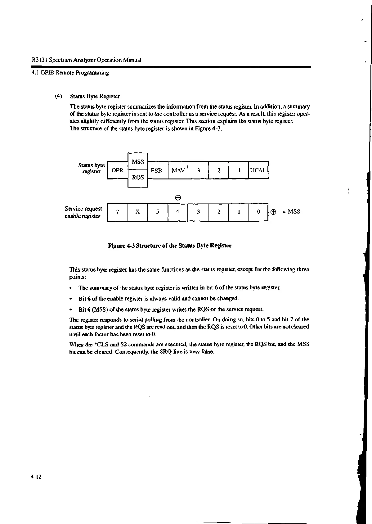
The status byte register summarizes the information from the status register. In addition, a summary
of the status byte register is sent to the controller as a service request. As a result, this register oper-
ates slightly differently from the status register. This section explains the status byte register.
The structure of the status byte register is shown in Figure 4-3.
Status byte
register
Service request
enable register
OPR
MSS
RQS
ESB MAV
3
2
1 UCAL
ED
Figure 4-3 Structure of the Status Byte Register
®—▶MSS
This status byte register has the same functions as the status register, except for the following three
points:
• The summary of the status byte register is written in bit 6 of the status byte register.
• Bit 6 of the enable register is always valid and cannot be changed.
• Bit 6 (MSS) of the status byte register writes the RQS of the service request.
The register responds to serial polling from the controller. On doing so, bits 0 to 5 and bit 7 of the
status byte register and the RQS are read out, and then the RQS is reset to O. Other bits are not cleared
until each factor has been reset to 0.
When the *CLS and S2 commands are executed, the status byte register, the RQS bit, and the MSS
bit can be cleared. Consequently, the SRQ line is now false.
4-12

 Loading...
