R3131 Spectrum Analyzer Operation Manual
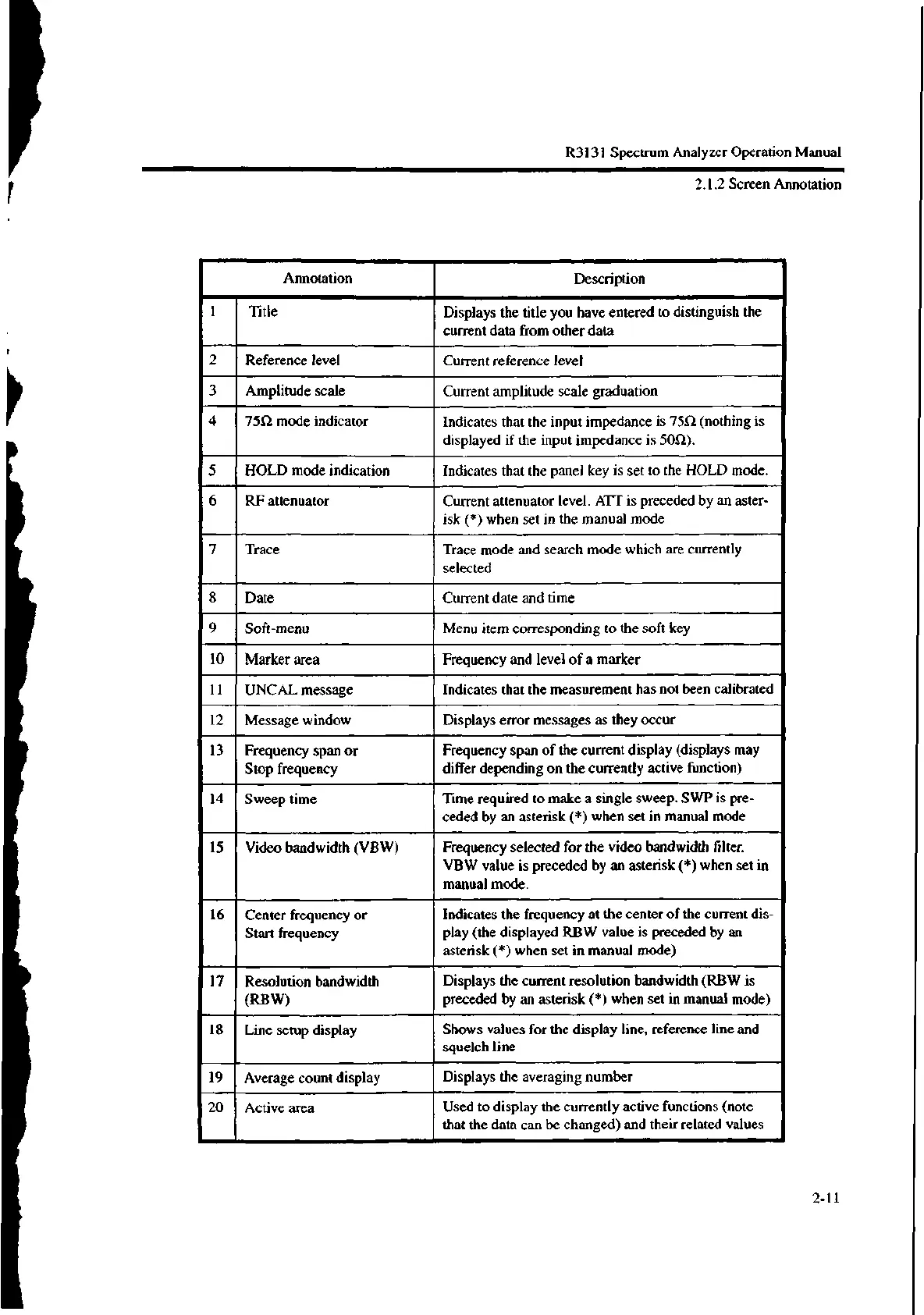
Annotation
Description
1
Title
Displays the title you have entered to distinguish the
current data from other data
2
Reference level
Current reference level
3
Amplitude scale
Current amplitude scale graduation
4
7551 mode indicator Indicates that the input impedance is 7552 (nothing is
displayed if the input impedance is 5052).
5
HOLD mode indication Indicates that the panel key is set to the HOLD mode.
6 RF attenuator
Current attenuator level. ATI' is preceded by an aster-
isk (*) when set in the manual mode
7 Trace
Trace mode and search mode which are currently
selected
8
Date Current date and time
9 Soft-menu Menu item corresponding to the soft key
10
Marker area Frequency and level of a marker
11
UNCAL message
Indicates that the measurement has not been calibrated
12 Message window
Displays error messages as they occur
13 Frequency span or
Stop frequency
Frequency span of the current display (displays may
differ depending on the currently active function)
14 Sweep time
Time required to make a single sweep. SWP is pre-
ceded by an asterisk (*) when set in manual mode
15
Video bandwidth (VBW)
Frequency selected for the video bandwidth filter.
VBW value is preceded by an asterisk (*) when set in
manual mode.
16 Center frequency or
Start frequency
Indicates the frequency at the center of the current dis-
play (the displayed RBW value is preceded by an
asterisk (*) when set in manual mode)
17
Resolution bandwidth
(RBW)
Displays the current resolution bandwidth (RBW is
preceded by an asterisk (*) when set in manual mode)
18 Line setup display
Shows values for the display line, reference line and
squelch line
19
Average count display
Displays the averaging number
20
Active area
Used to display the currently active functions (note
that the data can be changed) and their related values
2.1.2 Screen Annotation
2-11

 Loading...
