R3131 Spectrum Analyzer Operation Manual
Control
Description
8
AC power connector
3-pin type
9
Fuse holder
Holds the line fuse and one spare fuse which is supplied
with the spectrum analyzer
10
Fuse information
Lists the line voltages and fuse requirements
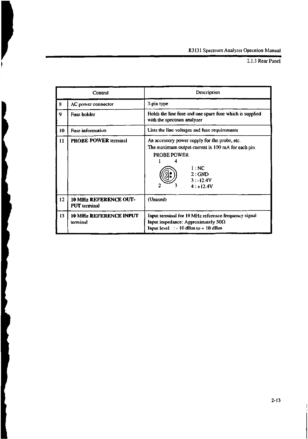
11 PROBE POWER terminal
An accessory power supply for the probe, etc.
The maximum output current is 100 mA for each pin.
PROBE POWER
1 4
1 : NC
1: 2 : GND
3 : -12.4V
2 3 4 : +12.4V
12 10 MHz REFERENCE OUT-
PUT terminal
(Unused)
13
10 MHz REFERENCE INPUT
terminal
Input terminal for 10 MHz reference frequency signal
Input impedance: Approximately 5052
Input level : - 10 dBm to + 10 dBm
2.1.3 Rear Panel
2-13

 Loading...
