EasyManuals Logo
Home>Allen-Bradley>Controller>20F

Allen-Bradley 20F Installation Instructions

Allen-Bradley 20F
320 pages
To Next Page IconTo Next Page
To Previous Page IconTo Previous Page
Page #128 background imageLoading...
Page #128 background image
128 Rockwell Automation Publication 750-IN001P-EN-P - April 2017
Chapter 3 Lift and Mount the Drive
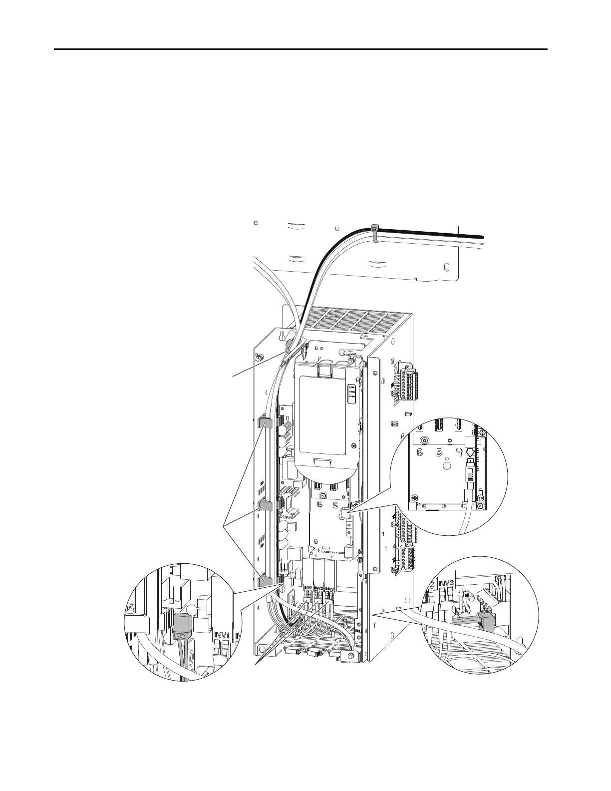
2. Disconnect the HIM cable (see number 1).
3. Disconnect the 24V wire harness from TB1 and P14 on the fiber
interface board (see number 2).
4. Disconnect any fiber-optic cables from the fiber interface board. This
step is not necessary on Frame 8 drives (see number 3).
5. Unlock the three cable supports along the left inside wall of the drive
control pod (see number 4).
6. Open the releasable cable tie at the top of the drive control pod (see
number 5).
TB1
P14
1
4
5
2
2
3

Table of Contents

Other manuals for Allen-Bradley 20F

Questions and Answers:

Question and Answer IconNeed help?

Do you have a question about the Allen-Bradley 20F and is the answer not in the manual?

Allen-Bradley 20F Specifications

General IconGeneral
BrandAllen-Bradley
Model20F
CategoryController
LanguageEnglish

Related product manuals