240 Rockwell Automation Publication 750-IN001P-EN-P - April 2017
Chapter 5 I/O Wiring
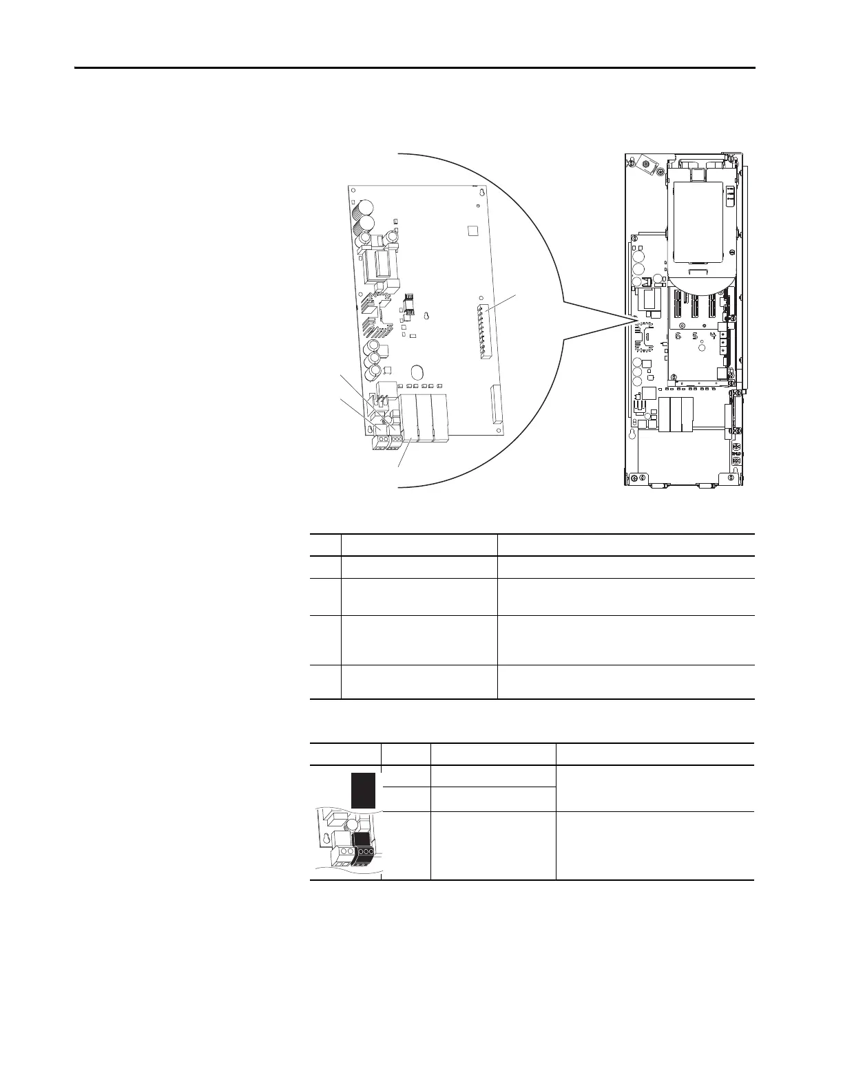
PowerFlex 755 Fiber-optic
Interface Board
This section provides details for the PowerFlex 755 fiber-optic interface board.
Figure 133 - Floor Mount Frames 8…10
Table 61 - Fiber-optic Interface Board Details
Table 62 - P13 Terminal Designations
No. Name Description
1 Main control board connector 98-pin main control board interface connection.
2 P13 Connections for user-supplied 24V power.
Powers control circuits when main power is removed.
3 P14 Connections for internal drive-supplied 24V power. Connection is
factory-wired and must not be modified.
Powers control circuits when main power is connected.
4 Inverter connections Fiber-optic ports: P1 = INV1, P2 = INV2, P3 = INV3, P4 = INV4,
P5 = INV5
Power Block Terminal Name Description
AP+ +24V auxiliary power Connections for customer supplied power supply:
24V DC ±10%, 5 A, PELV (protective extra low
voltage) or SELV (safety extra low voltage)
AP– Auxiliary power common
Sh Shield Terminating point for wire shields.
P1 P2 P3
SK-R1-FIB1-F8
1
2
3
4
 Loading...

