280 Rockwell Automation Publication 750-IN001P-EN-P - April 2017
Chapter 5 I/O Wiring
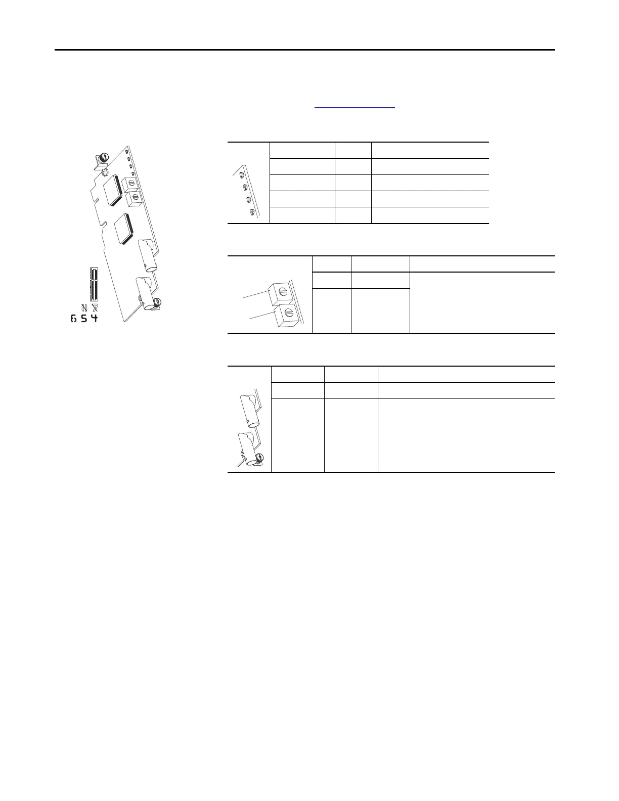
ControlNet Option Module
For complete information on the ControlNet option module, see the
PowerFlex 20-750-CNETC Coaxial ControlNet Option Module User
Manual, publication 750COM-UM003
.
Table 92 - ControlNet Option Module Status Indicator Indication
Table 93 - ControlNet Option Module Rotary Switches
Table 94 - Coax Receptacles
Status Indicator Name Description
1 PORT DPI Connection Status
2 MOD Option Module Status
3 NET A ControlNet Channel A Status
4 NET B ControlNet Channel B Status
Switch Name Description
1 TENS Switch Sets the node address of the option module.
2ONES Switch
Receptacle Name Description
1 Channel A Channel A BNC connection to the network.
2 Channel B Channel B (redundant) BNC connection to the network.
1
2
3
4
1
2
 Loading...

