200 Rockwell Automation Publication 750-IN001P-EN-P - April 2017
Chapter 4 Power Wiring
Input Power Circuit Breakers
and Disconnect Switches
See page 21 for an explanation of where to locate drive ratings on the
nameplate.
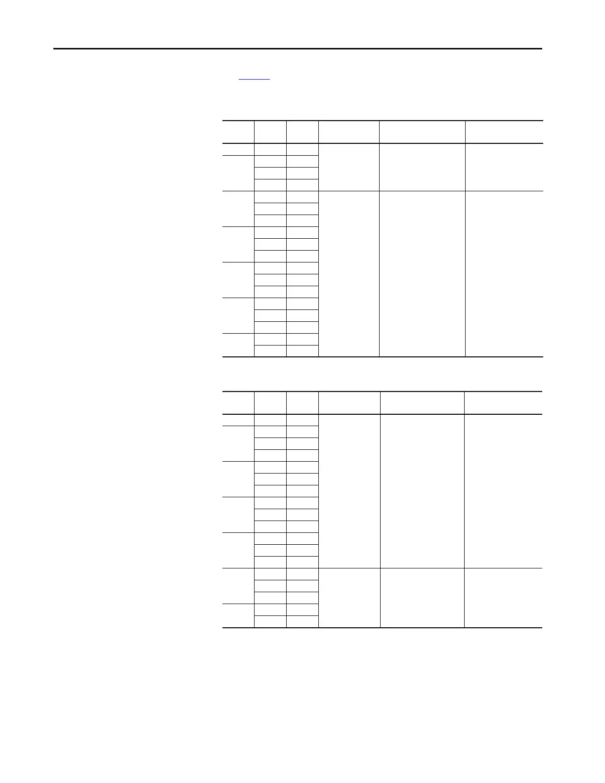
Table 31 - 400V, 50 Hz Input – Code P3 Thermal Magnetic Circuit Breaker Options
Table 32 - 400V, 50 Hz Input – Code P5 Molded Case Disconnect Switch Options (only floor
mount Frame 8)
kW Amps Duty Line Side Terminal
Lugs
Terminal Size Recommended Torque
N•m (lb•in)
200 385 Heavy
140G-M-TLA23 (2) 250…500 MCM kit of 3 31 (274)
250
460 Normal
456 Heavy
472 Heavy
315
540 Light
140G-N-TLA43 (4) 4/0…500 MCM 43 (381)
540 Normal
540 Heavy
315
585 Light
567 Normal
585 Heavy
355
612 Light
650 Normal
642 Heavy
400
750 Light
750 Normal
770 Normal
450
796 Light
832 Light
kW Amps Duty Line Side Terminal
Lugs
Terminal Size Recommended Torque
N•m (lb•in)
200 385 Heavy
140G-M-TLA23 (2) 250…500 MCM kit of 3 31 (274)
250
460 Normal
456 Heavy
472 Heavy
315
540 Light
540 Normal
540 Heavy
315
585 Light
567 Normal
585 Heavy
355
612 Light
650 Normal
642 Heavy
400
750 Light
140G-N-TLA43 (4) 4/0…500 MCM 43 (381)
750 Normal
770 Normal
450
796 Light
832 Light
 Loading...

