Rockwell Automation Publication 750-IN001P-EN-P - April 2017 241
I/O Wiring Chapter 5
Table 63 - P14 Terminal Designations
AC Input Drive Control and
Power Terminal Block
This section provides details for the AC input drive control and power
terminal block.
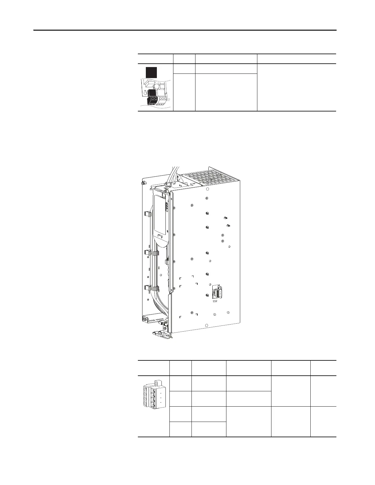
Figure 134 - Floor Mount Frames 8…10
Table 64 - TB2 Terminal Designations
Power Block Terminal Name Description
1 +24V power Connections for drive supplied power.
2 Power common
Fixed I/O Terminal Name Description Rating Related
Parameter
1SHUNT TRIP
COMMON
Output Relay common 125V AC, 10 A max,
1250VA Only
resistive
16 On port
11
2 SHUNT TRIP NO Output Relay normally
open contact.
3 FAN 240VAC OUT
NEUTRAL
Connections for cooling
fans.
240V AC, 50/60 Hz,
1.4 A, 336VA
4 FAN 240VAC OUT
HOT
AC Input Drive Control Panel
1
2
3
4
 Loading...

