304 Rockwell Automation Publication 750-IN001P-EN-P - April 2017
Chapter 5 I/O Wiring
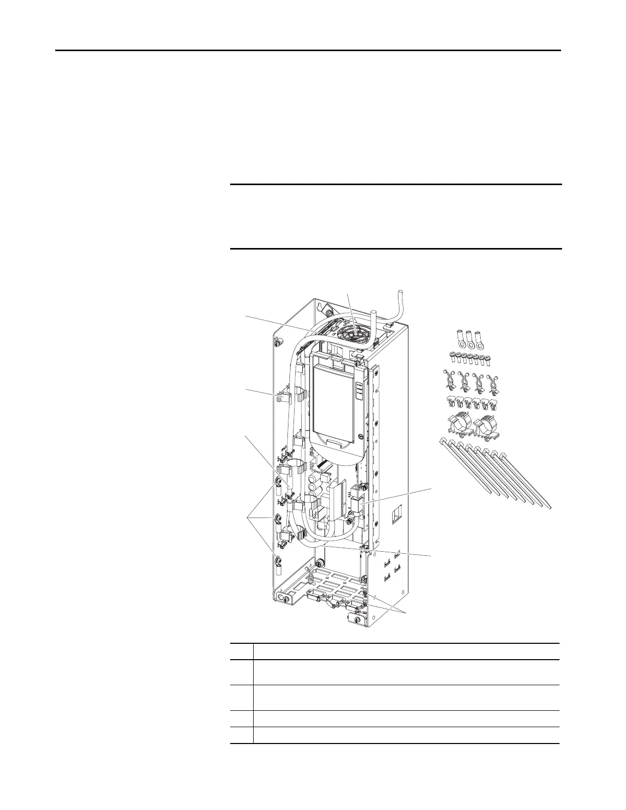
Control Pod Cable Routing
This section provides details for routing the control pod cable.
Floor Mount Frames 8…10
Supports, clips, and cable ties are provided to help route cabling inside the
control pod.
Figure 163 - Control POD Detail
IMPORTANT • When routing cabling into the control POD, do not block the cooling fan
outlet.
• Do not ground shield wires to the inner sheet metal bucket that supports
the option modules.
No. Description
1 I/O Signal shield termination points. Use M4 screws and ring terminals that are provided to tie together
and terminate drain wires and shields.
2 Ground shield wires to outer sheet metal bucket. Strip cable insulation 25 mm (1 in.) to expose braid.
Attach cable ties around shield and through slots. Pull tight.
3 Attachment points for cable management devices provided (six places).
4 Cable support ladder.
1
2
3
4
5
6
7
7
6
8
 Loading...

