EasyManuals Logo
Home>Allen-Bradley>Controller>20F

Allen-Bradley 20F Installation Instructions

Allen-Bradley 20F
320 pages
To Next Page IconTo Next Page
To Previous Page IconTo Previous Page
Page #51 background imageLoading...
Page #51 background image
Rockwell Automation Publication 750-IN001P-EN-P - April 2017 51
Lift and Mount the Drive Chapter 3
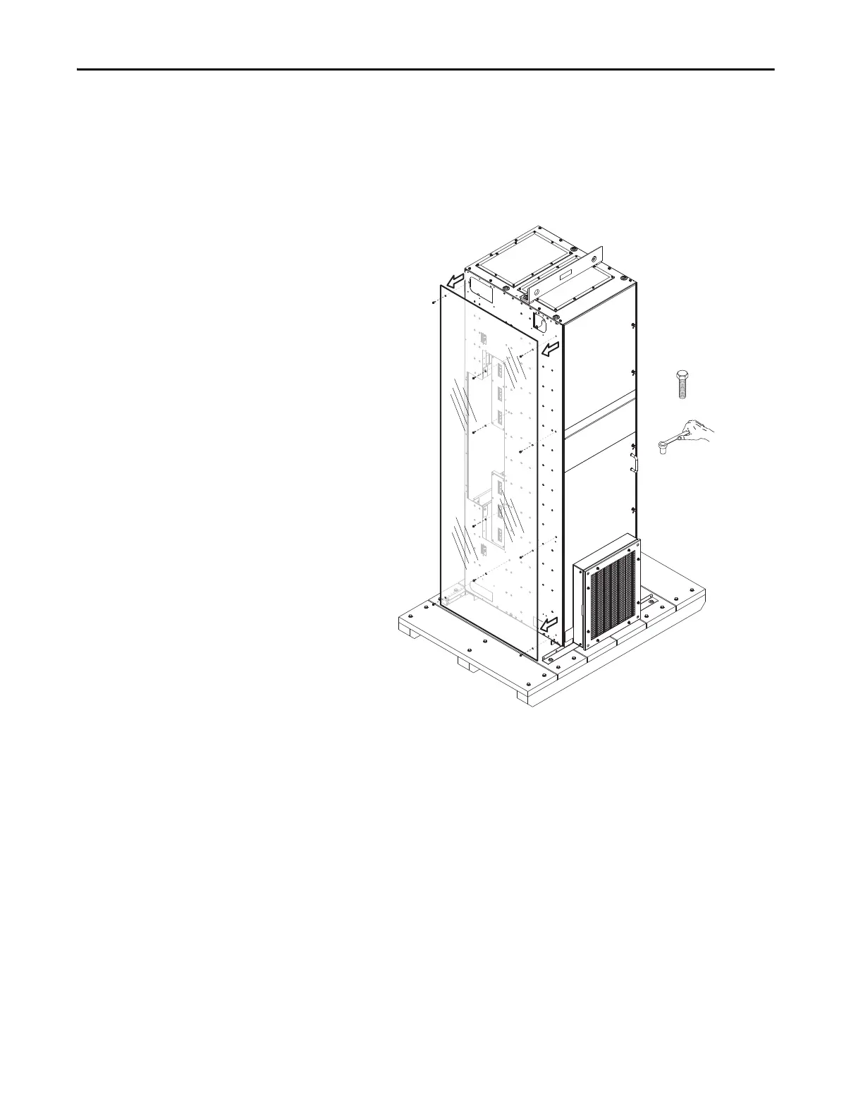
Position the Wiring Bay
To position the wiring bay, follow these steps.
1. Remove and discard the screws that hold the protective panel against the
left side of the wiring bay.
2. Remove and discard the protective panel.
M6 x 13
10 mm
IP54, NEMA 12 Enclosure Rating Shown

Table of Contents

Other manuals for Allen-Bradley 20F

Questions and Answers:

Question and Answer IconNeed help?

Do you have a question about the Allen-Bradley 20F and is the answer not in the manual?

Allen-Bradley 20F Specifications

General IconGeneral
BrandAllen-Bradley
Model20F
CategoryController
LanguageEnglish

Related product manuals