Rockwell Automation Publication 750-IN001P-EN-P - April 2017 257
I/O Wiring Chapter 5
11-Series I/O Option Module
Wiring Examples
This section provides examples for how to wire the 11-Series I/O option
module.
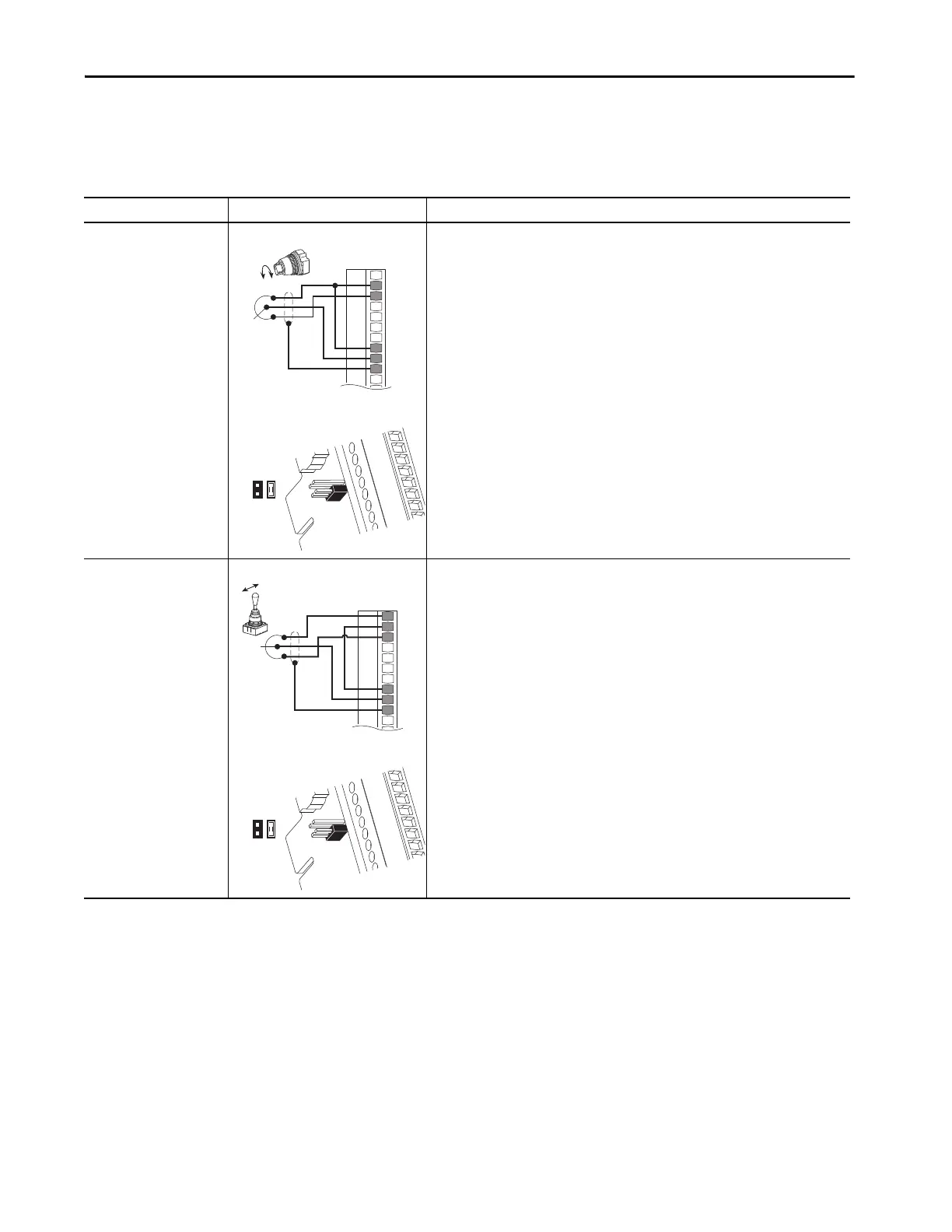
Table 76 - 11-Series I/O Option Module TB1 Wiring Examples
Input/Output Connection Example Required Parameter Changes
Potentiometer Unipolar
Speed Reference
10 kΩ Pot. Recommended
(2 kΩ Minimum)
11-Series I/O Module TB1
•Set direction mode
Port 0: P308 [Direction Mode] = 0 “Unipolar”
•Set selection
Port 0: P545 [Spd Ref A Sel] = Port X (11-Series I/O Module): P50 [Anlg In0 Value]
•Adjust scaling
Port X (11-Series I/O Module): P51 [Anlg In0 Hi] = 10V
Port X (11-Series I/O Module): P52 [Anlg In0 Lo] = 0V
Port 0: P547 [Spd Ref A AnlgHi] = 60 Hz
Port 0: P548 [Spd Ref A AnlgLo] = 0 Hz
•View results
Port X (11-Series I/O Module): P50 [Anlg In0 Value]
Port 0: P592 [Selected Spd Ref]
Joystick Bipolar Speed
Reference
±10V Input
11-Series I/O Module TB1
•Set direction mode
Port 0: P308 [Direction Mode] = 1 “Bipolar”
•Set selection
Port 0: P545 [Spd Ref A Sel] = Port X (11-Series I/O Module): P50 [Anlg In0 Value]
•Adjust scaling
Port X (11-Series I/O Module): P51 [Anlg In0 Hi] = +10V
Port X (11-Series I/O Module): P52 [Anlg In0 Lo] = -10V
Port 0: P547 [Spd Ref A AnlgHi] = +60 Hz
Port 0: P548 [Spd Ref A AnlgLo] = -60 Hz
•View results
Port X (11-Series I/O Module): P50 [Anlg In0 Value]
Port 0: P592 [Selected Spd Ref]
P5
1
2
P4
1
2
P5
1
2
P4
1
2
 Loading...

