Rockwell Automation Publication 750-IN001P-EN-P - April 2017 277
I/O Wiring Chapter 5
• Set Universal Feedback parameter P6 [FB0 Device Sel] and/or P36
[FB1 Device Sel] to a Sine/Cosine type device.
Auxiliary Power Supply
Option Module
This section provides details for the auxiliary power supply option module.
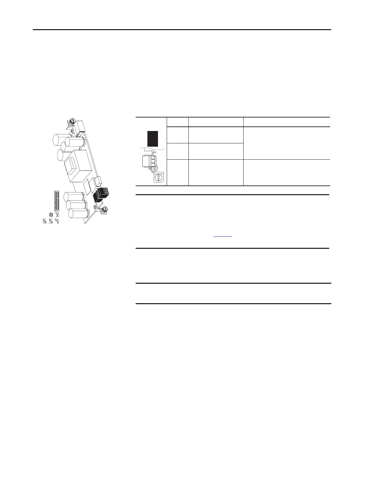
Table 88 - TB1 Terminal Designations
A connector cable is provided with auxiliary power supply option modules for
use in PowerFlex 753 drives. The cable is used to connect the module to the
backplane when installed on the upper control pod brackets.
20-750-APS
Terminal Name Description
AP+ +24V Auxiliary Power Connections for customer supplied power supply:
24V DC ±10%, 3 A, PELV (Protective Extra Low
Voltage) or SELV (Safety Extra Low Voltage)
AP– Auxiliary Power Common
Sh Shield Terminating point for wire shields when an EMC
plate or conduit box is not installed.
IMPORTANT The auxiliary power supply option module can be installed in any option
port. Due to its size, the module extends over and block and adjacent port.
Therefore, installation in Port 8 is recommended.
Do not use the auxiliary power supply option module with Frame 8 and
larger drives. See page240
for information on how to connect an external
power supply to Frame 8 and larger drives.
IMPORTANT The connector cable is used with PowerFlex 755 Frame 1 drives. The cable is
not used with PowerFlex 755 Frame 2 and larger drives.
AP+
AP–
Sh
AP+
AP-
Sh
 Loading...

