Rockwell Automation Publication 750-IN001P-EN-P - April 2017 157
Power Wiring Chapter 4
Three-phase Terminal
Locations
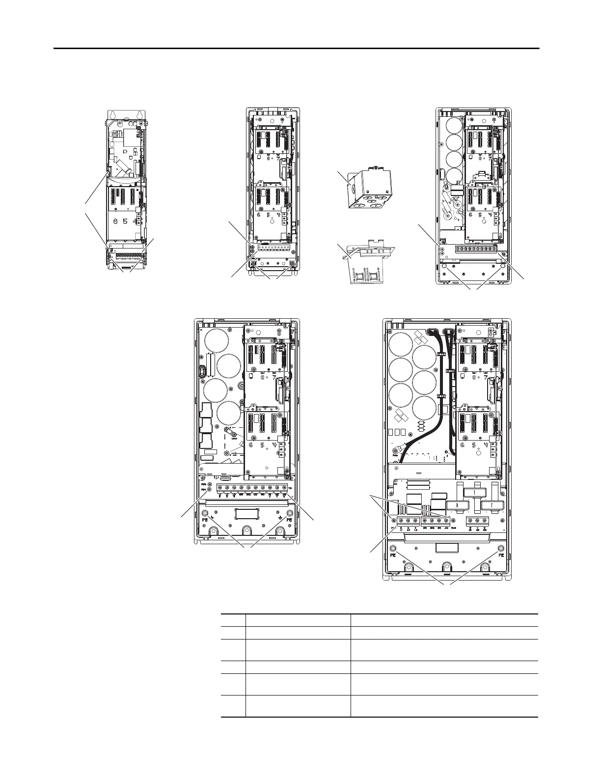
This section shows the locations of the power block and termination points.
Figure 95 - Wall Mount Frames 1…5 Power Terminal Block and Termination Point Locations
Wall Mount Frame 2
Wall Mount Frame 3
Wall Mount Frame 4
Wall Mount Frame 5
Wall Mount Frame 1
No. Name Description
1 Power terminal block R/L1, S/L2, T/L3, BR1, BR2, +DC, -DC, U/T1, V/T2, W/T3
2 PE grounding studs Terminating point to chassis ground for incoming AC line and
motor shields.
3 PE-A and PE-B MOV and CMC jumpers
4 Optional NEMA/UL Type 1 conduit
box
Terminating point to chassis ground for incoming AC line, motor
shields, and control wire shields.
5 Optional EMC plate Terminating point to chassis ground for incoming AC line, motor
shields, and control wire shields.
 Loading...

