Rockwell Automation Publication 750-IN001P-EN-P - April 2017 199
Power Wiring Chapter 4
Transformer Panel
There are cabinet options for fuses and thermostat.
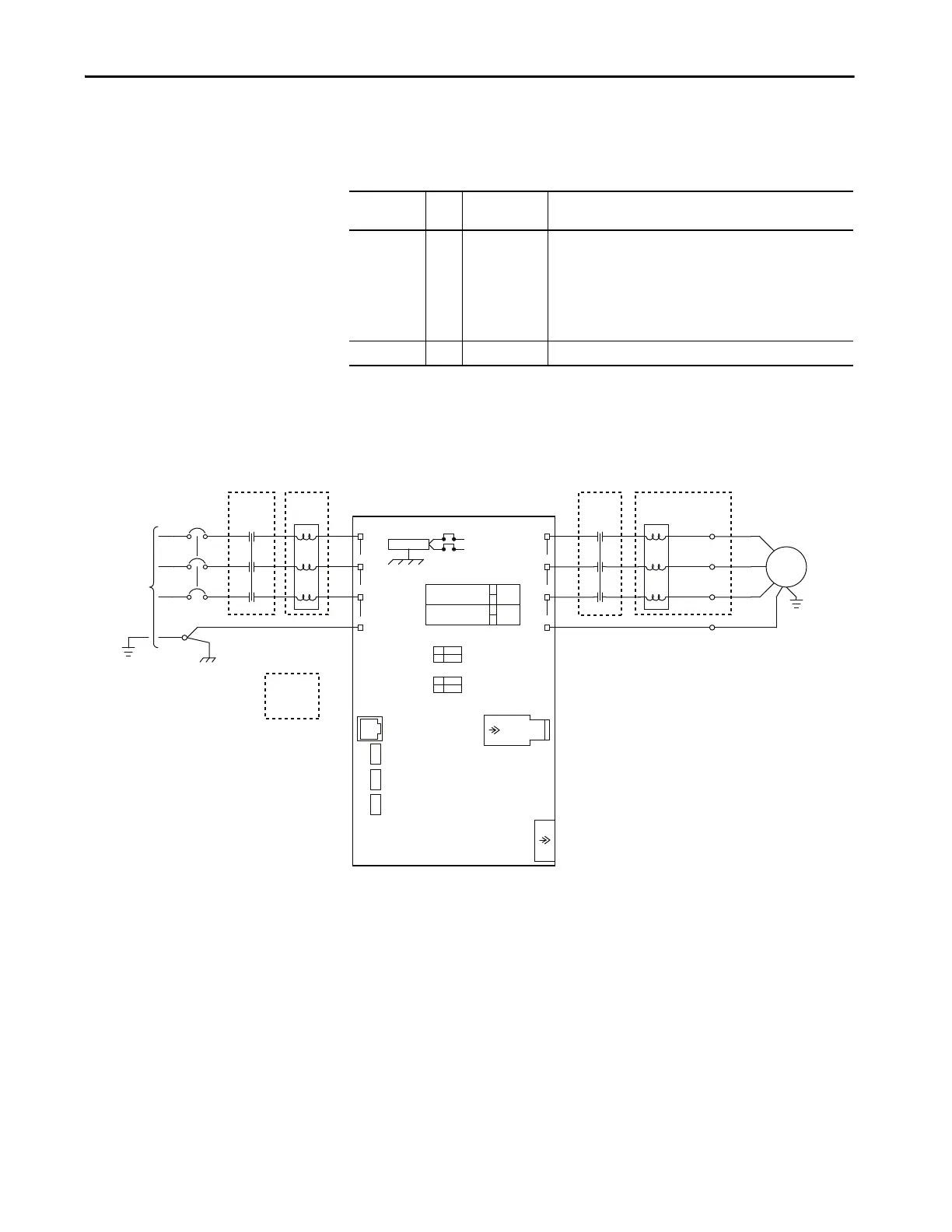
Power Wiring Schematic
This figure shows the power wiring.
Option Code Applicable
Frame
Description
Fuses – 8 (only IP54
enclosures)
9 (all enclosures)
FU9, FU10 (690V AC)
FU9, FU10 (400, 480, 600V AC)
FU11
FU12 (120V AC)
FU12 (230V AC)
FU13 (Frame 8 with P11 or P12 Only)
690V AC, 6 A, IEC gl-gG
600V AC, 6 A, Class CC
600V AC, 5 A, Class CC
600V AC, 6 A, Class CC
600V AC, 3 A, Class CC
600V AC, 5 A, Class CC
Thermostat – 8 and 9 Thermostat is used in all option bays and enclosure types.
LINE-PE
CHASSIS
INPUT
VOLTAGE,
3PH,
AC LINES
X
X
TB1
CHASSIS
PE-A
PE-B
COMMON MODE CAP JPR
TB1
MOV/AC EMI CAP JPR
DPI
PORT 2
SEE USER MANUAL
DPI
PORT 1
MOV/AC EMI
COMMON MODE
IN
IN
OUT
OUT
SETTINGS
AS SHIPPED
CAP JUMPER
CAP JUMPER
HUNDREDS
TENS
ONES
J1 HARDWARE ENABLE
IN
EMBEDDED ETHERNET
ADAPTER ROTARY
SWITCHES
AS SHIPPED
SETTINGS
OUT
J2 SAFETY ENABLE
IN
OUT
J12
SETTINGS
AS SHIPPED
J11
PE
T3/W
T2/V
T1/U
PE-B
L3/T
L2/S
LI/R
EA1
POWERFLEX 755 POWER MODULE
J6
EMBEDDED ETHERNET
9
9
9
X
X
M
GND
T1/T6
T2/T4
T3/T5
L1
L2
L3
MTR-PE
INPUT
REACTOR
INPUT
CONTACTOR
INPUT
CIRCUIT
BREAKER
MOTOR
Optional
Devices
OUTPUT
REACTOR
OUTPUT
CONTACTOR
(Frame 8 Only)
OUTPUT
TERMINAL
 Loading...

