232 Rockwell Automation Publication 750-IN001P-EN-P - April 2017
Chapter 5 I/O Wiring
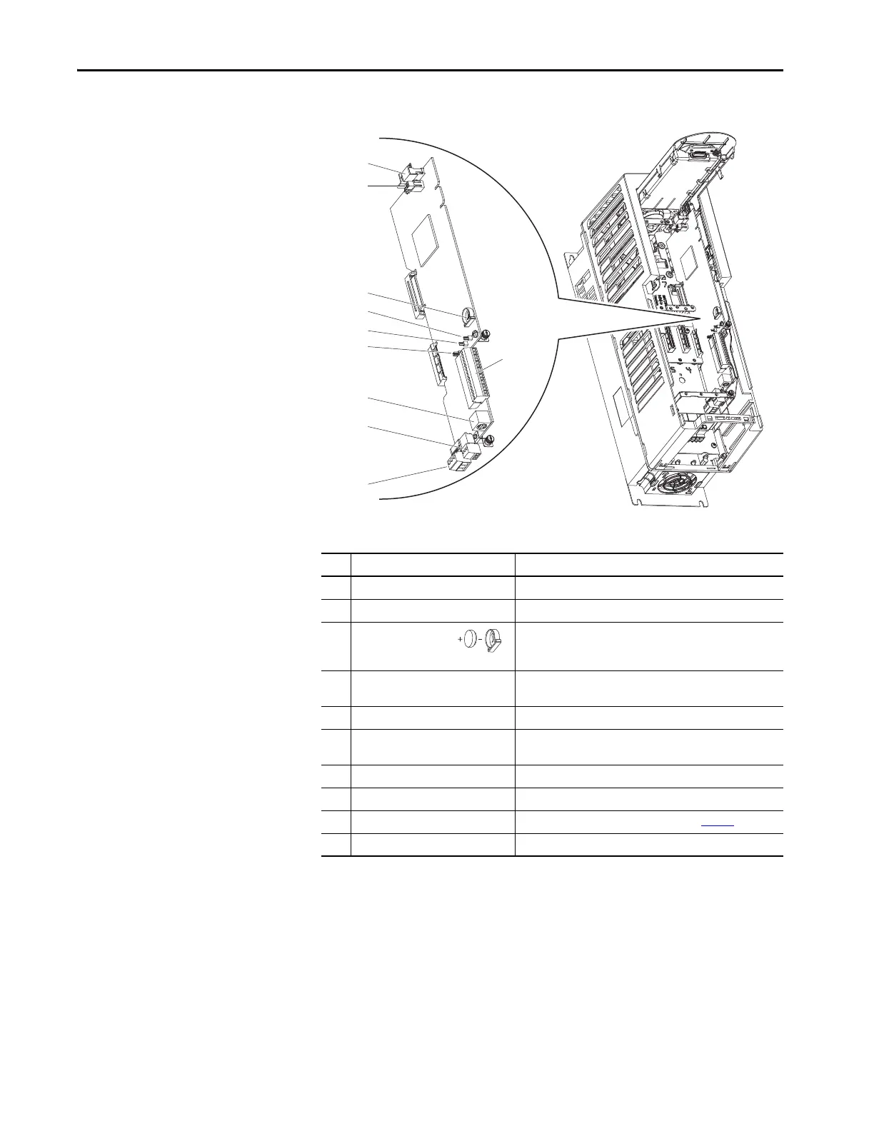
PowerFlex 753 Main Control
Board
This section provides details for the PowerFlex® 753 main control board.
Table 52 - PowerFlex 753 Main Control Board Details
No. Name Description
1 HIM connector DPI™ port 1 (HIM cradle) connection.
2 Fan connector Power supply for internal cooling fan (Frames 2 and 3).
3 Battery receptacle User installed CR1220 lithium coin cell battery provides power to
the real-time clock (optional, not supplied). Preserves the real-
time clock setting in the event power to the drive is lost or cycled.
4 ENABLE jumper Hardware enable jumper. TB3 becomes an Enable when this
jumper is removed.
5 SAFETY jumper Safety enable jumper. Removed when safety option is installed.
6 Jumper J4 input mode Analog input mode jumper. Selects voltage mode or current
mode.
7 TB1 I/O terminal block.
8 DPI™ port 2 Cable connection for handheld and remote HIM options.
9 TB3 Digital input terminal block. See Important at Table 56
.
10 TB2 Relay terminal block.
SK-R1-MCB1-PF753
1
2
3
4
5
6
8
9
10
7
 Loading...

