236 Rockwell Automation Publication 750-IN001P-EN-P - April 2017
Chapter 5 I/O Wiring
Table 58 - TB1 I/O Terminal Designations
Floor Mount Frames 8…10
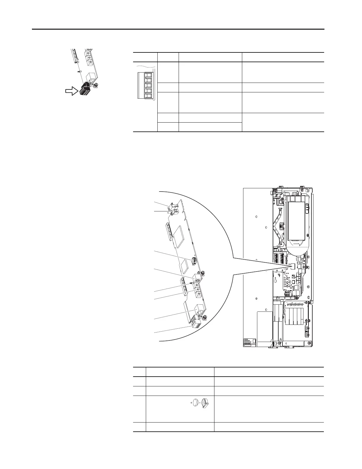
This section provides details for the PowerFlex 755 main control board, frames
8…10.
Table 59 - Control Board Details
Fixed I/O Terminal Name Description
Di 0ac Digital input 0
120V AC (132V AC max)
Connections for AC power supply.
High state: 100…132V AC
Low state: 0…30V AC
Di C Digital input common Digital input common
Di 0dc Digital input 0
24V DC (30V DC max)
Connections for DC power supply.
High state: 20…24V DC
Low state: 0…5V DC
+24V +24V power (50 m [164 ft] A max) Connections for drive supplied 24V power.
24VC 24V common
No. Name Description
1 HIM connector DPI port 1 (HIM Cradle) connection.
2 Fan connector Power supply for internal cooling fan.
3 Battery receptacle User installed CR1220 lithium coin cell battery provides power to
the real-time clock (optional, not supplied).
Preserves the real-time clock setting in the event power to the
drive is lost or cycled.
4 DPI port 2 Cable connection for handheld and remote HIM options.
 Loading...

