254 Rockwell Automation Publication 750-IN001P-EN-P - April 2017
Chapter 5 I/O Wiring
11-Series I/O Option Module
This section provides a description of the 11-Series I/O option module.
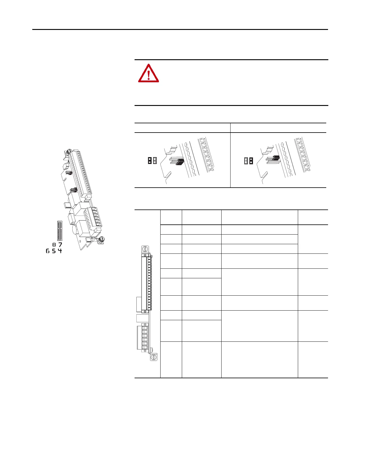
Table 71 - Analog Input Mode Jumpers
ATTENTION: When used in an Integrated Motion on EtherNet/IP networks
application for Firmware, versions 12 and later, the 11-series module must
be installed only in port 7.
Note that you cannot use the ATEX card with the 11-series I/O card in port 7
when used in an Integrated Motion on EtherNet/IP application.
20-750-1132C-2R (24 Volts DC)
20-750-1133C-1R2T (24 Volts DC)
20-750-1132D-2R (120 Volts AC)
Voltage Mode Current Mode
Table 72 - TB1 Terminal Designations
Terminal Name Description Related
Parameter
(4)
–10V –10V reference Negative 10V DC for analog inputs. 2 kΩ min
10VC 10V common For (–) and (+) 10V references.
+10V +10V reference Positive 10V DC for analog inputs. 2 kΩ min
Sh Shield Terminating point for wire shields when an
EMC plate or conduit box is not installed.
Ao0– Analog out 0 (–) Bipolar, ±10V, 11 bit and sign, 2 kΩ min
load.
4…20 mA, 11 bit and sign, 400 Ω max
load.
75
On port X
Ao0+ Analog out 0 (+)
Sh Shield Terminating point for wire shields when an
EMC plate or conduit box is not installed.
Ai0– Analog input 0 (–) Differential
(2)
, bipolar, 11 bit and sign.
Voltage Mode: ±10V at 88 kΩ input
impedance.
Current Mode: 0…20 mA at 93 Ω input
impedance.
50, 70
On port X
Ai0+ Analog input 0 (+)
Sh Shield Terminating point for wire shields when an
EMC plate or conduit box is not installed.
P5
1
2
P4
1
2
–10V
10VC
+10V
Sh
Ao0–
Ao0+
Sh
Ai0–
Ai0+
Sh
Di0
Di0P
Di1
Di1P
Di2
Di2P
Ip
Ic
EnC
EnNO
 Loading...

