Rockwell Automation Publication 750-IN001P-EN-P - April 2017 285
I/O Wiring Chapter 5
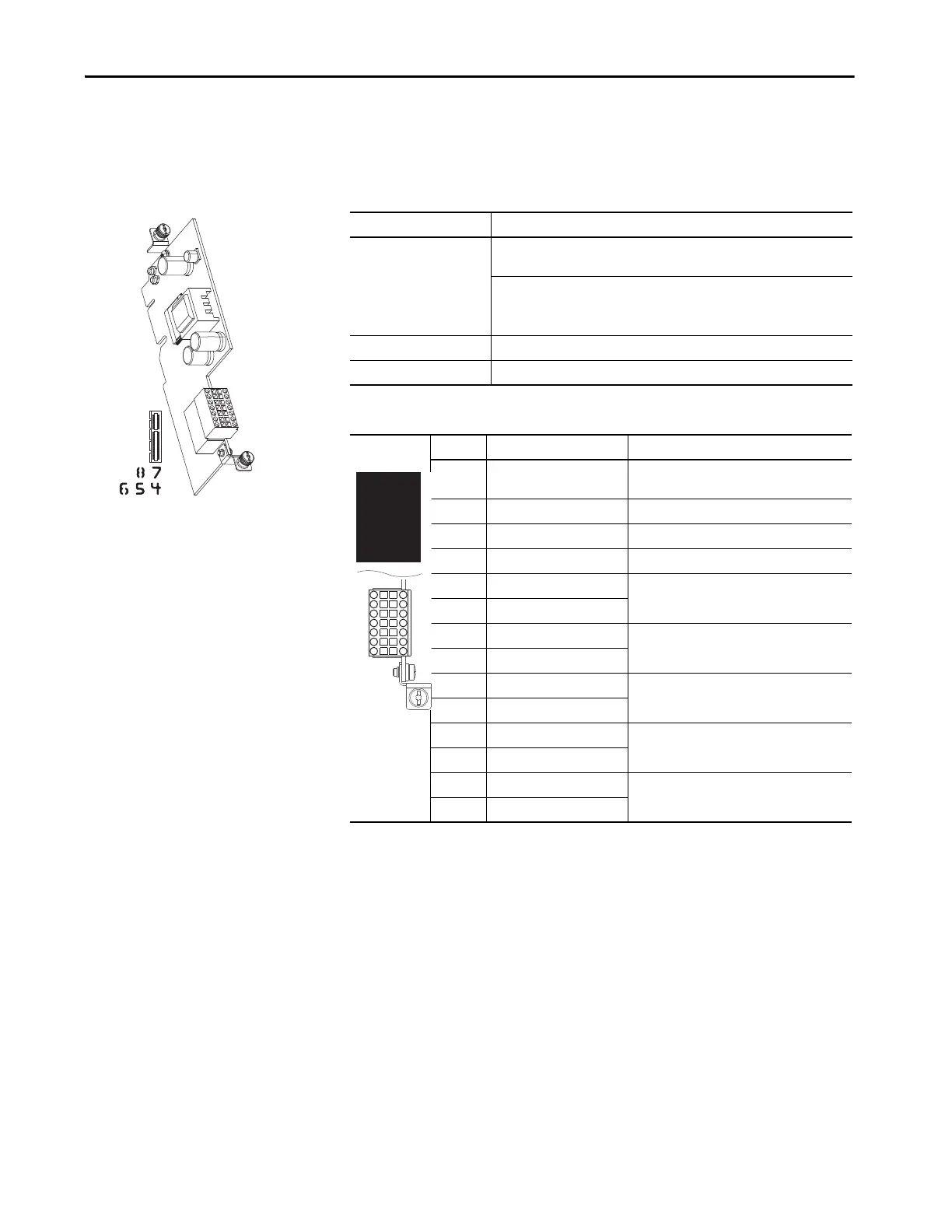
Single Incremental Encoder
Option Module
This section provides details for the single incremental encoder option module.
Table 107 - Single Incremental Encoder Specifications
Table 108 - TB1 Terminal Designations
Consideration Description
Input Differential or Single Ended operation, Constant Current Sink operation,
approx 10 mA
5V DC min to 15V DC max sourcing 10 mA
Minimum high state voltage of 3.5V DC
Maximum low state voltage of 0.4V DC
Maximum Cable Length 30 m (100 ft) at 5V, 183 m (600 ft) at 12V
Maximum Input Frequency 250 kHz
Terminal Name Description
Sd Shield Terminating point for wire shields when an EMC
plate or conduit box is not installed.
12 +12 Volt DC Power Power supply for encoder 250 mA.
Com Common +12V and +5V Common
5 +5 Volt DC Power Power supply for encoder 250 mA.
A Encoder A Single channel or quadrature A input.
A- Encoder A (NOT)
B Encoder B Quadrature B input.
B- Encoder B (NOT)
Z Encoder Z Pulse or marker input.
Z- Encoder Z (NOT)
+24 +24 Volt Power source for homing input.
24C Common
HmC Homing Input Common Captures the AB edge counter.
Hm Homing Input
Sd
Com
A
B
Z
+24
HmC
12
5
A-
B-
Z-
24C
Hm
 Loading...

