Rockwell Automation Publication 750-IN001P-EN-P - April 2017 129
Lift and Mount the Drive Chapter 3
7. Without bending the cables to a radius less than 50 mm (2 in.), lift the
24V wire harness and fiber-optic cables out of the drive control pod.
Support the cable bundle so it is out of the way of the drive assembly
when it is rolled out of the cabinet.
Disconnect Wire Connections
– No Drive Control Pod
This procedure applies to Frame 8 drives with a remotely mounted drive
control pod (up to 23 m [75 ft] away) and to the cabinets on the right side of
Frame 9 and larger drives.
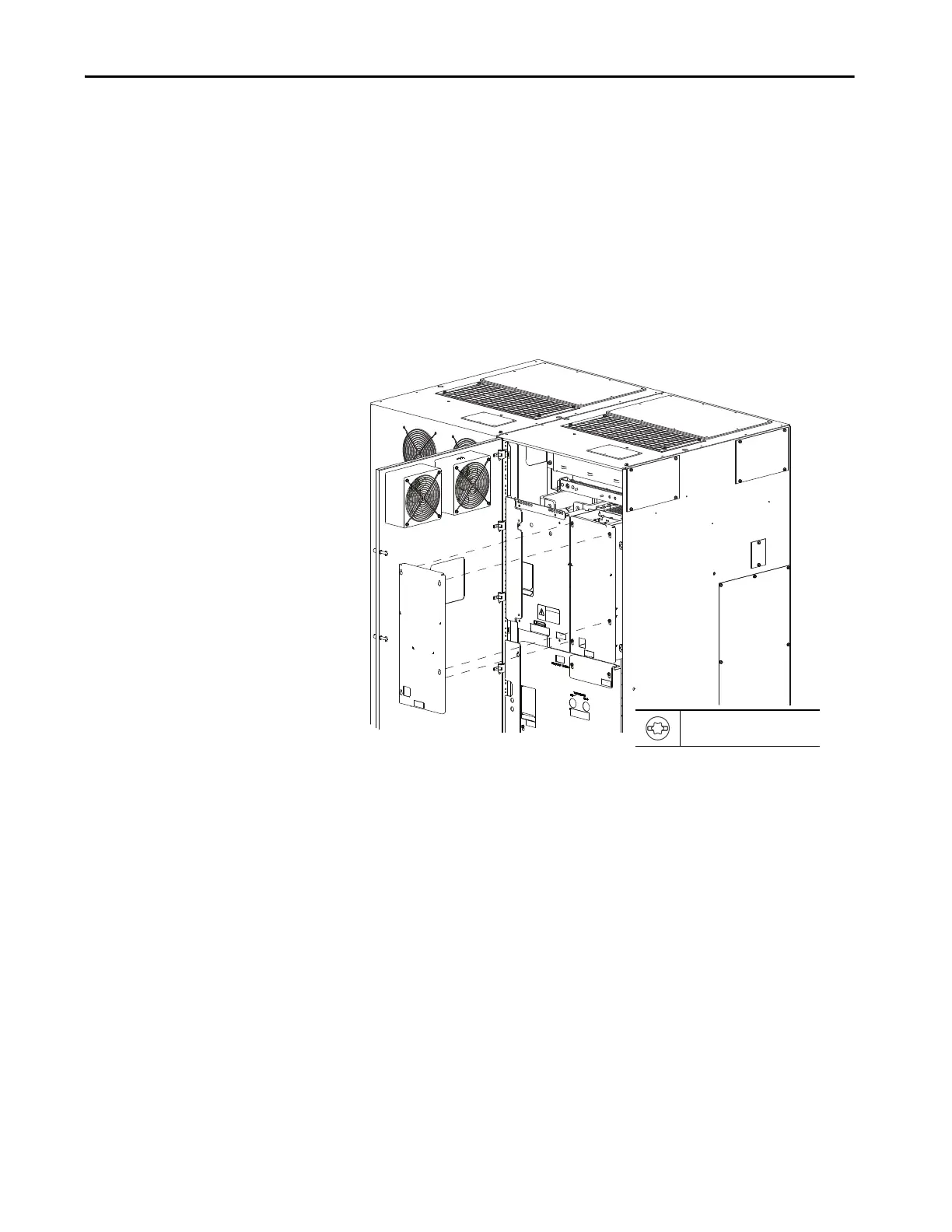
1. Remove the right front cover.
2. Disconnect the 24V wire harness from TB1 (see number 1).
3. Disconnect the fiber-optic cable from INV on the power layer interface
board (see number 2).
T20 or F 6.4 mm (0.25 in.)
1.8 N•m (16.0 lb•in)
Floor Mount Frame 9 Shown
 Loading...

