Rockwell Automation Publication 750-IN001P-EN-P - April 2017 167
Power Wiring Chapter 4
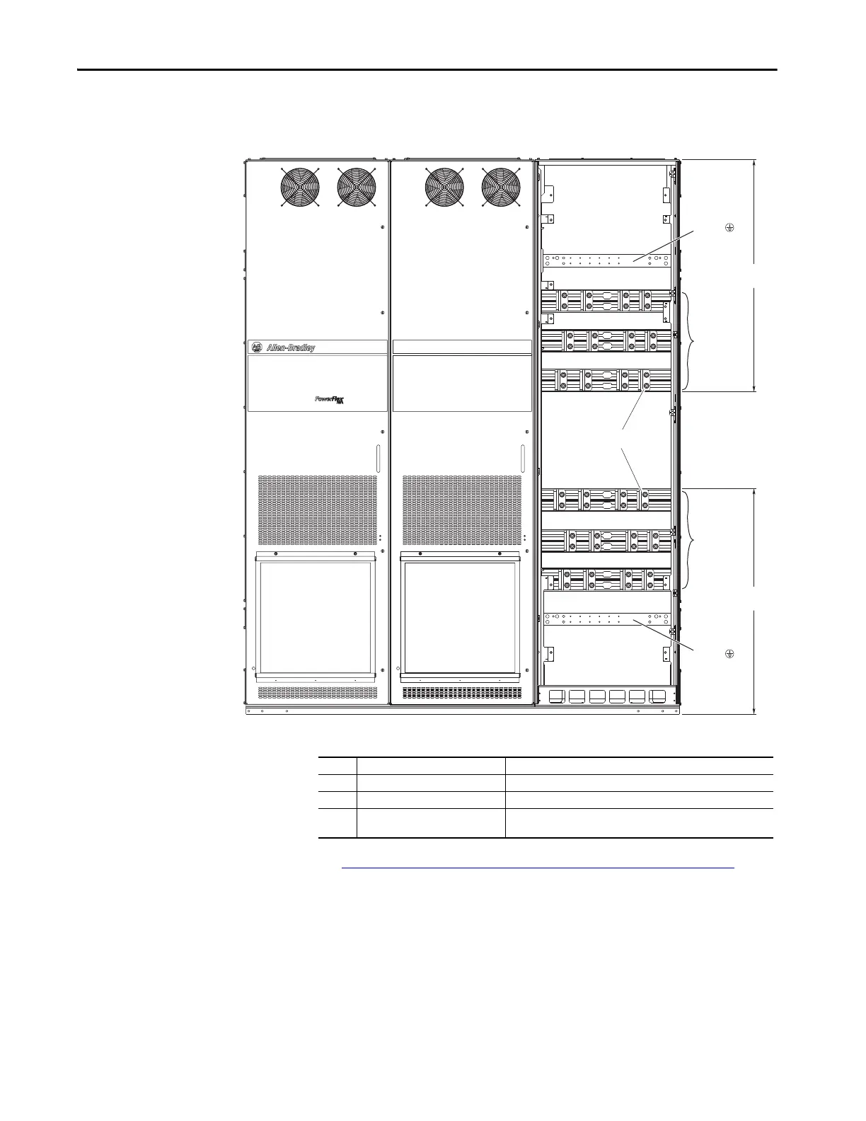
Floor Mount Cabinet Options
Bay
Figure 101 - Bus Bar Locations, Floor Mount Frame 9 Cabinet Options Bay (Cabinet Options
Assembly Removed)
Table 18 - Floor Mount Frame 9 Cabinet Options Bay Bus Bars
See Floor Mount Frames 8…10 Power Terminal L-brackets on page 170 for
information on how to make cable connections on extruded bus bars.
R / L1
S / L2
T / L3
U / T1
V / T2
W / T3
PE
PE
964
(38.0)
936
(36.9)
3
3
2
1
No. Name Description
1 Power bus R/L1, S/L2, T/L3
2 Power bus U/T1, V/T2, W/T3
3 PE grounding bar Terminating point to chassis ground for incoming AC line and motor
shield.
 Loading...

