48 Rockwell Automation Publication 750-IN001P-EN-P - April 2017
Chapter 3 Lift and Mount the Drive
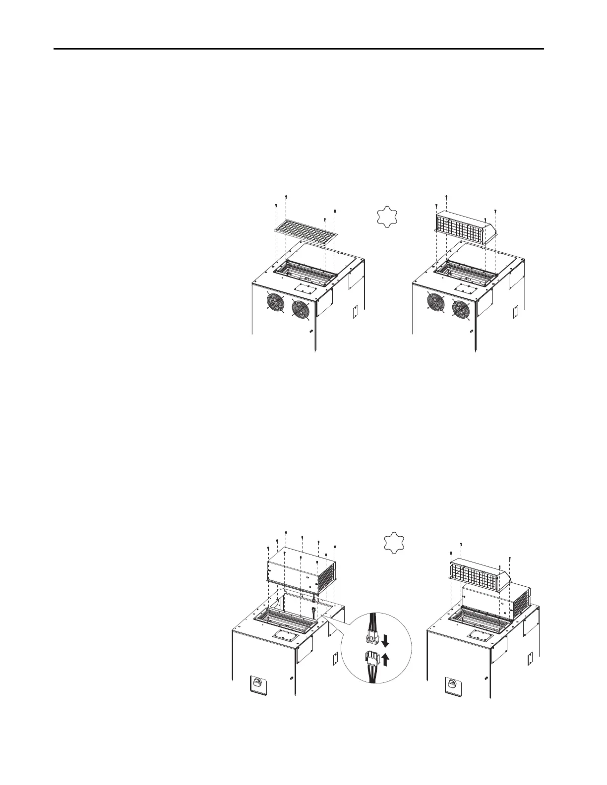
Install IP20, NEMA/UL Type 1
Debris Screen, or Optional
Exhaust Hood
IP20, NEMA/UL Type 1 drives are equipped with a top mounted debris
screen. An optional exhaust hood is also available as a kit (catalog number
20-750-HOOD1-F8).
1. Install the supplied debris screen over the exhaust vent.
(Or install the optional exhaust hood with the grill that faces the front of
the drive.)
2. Secure with the four screws provided.
Install IP54, NEMA 12 Cabinet
Blower Assembly and
Exhaust Hood
IP54, NEMA 12 drives are equipped with top a mounted blower assembly and
exhaust hood.
1. Install the cabinet blower assembly. Note the required power
connection.
2. Secure with the ten screws provided.
3. Install the exhaust hood with the grill that faces the front of the drive.
4. Secure with the four screws provided.
4.0 N•m (35 lb•in)
T25
Debris Screen (Supplied) Exhaust Hood (Optional Kit)
4.0 N•m (35 lb•in)
T25
 Loading...

