Rockwell Automation Publication 750-IN001P-EN-P - April 2017 237
I/O Wiring Chapter 5
Table 60 - TB1 I/O Terminal Designations
Hardware Enable Circuitry
Each main control board has one digital input, digital input 0, which can be
used as a general-purpose programmable input. Or you can remove a jumper to
configure as a dedicated hardware enable, which is unaffected by parameter
settings.
• PowerFlex 753 – digital input 0 is found on TB3
• PowerFlex 755 – digital input 0 is found on TB1
To configure digital input 0 as a dedicated hardware enable, follow these steps.
1. Access the control pod as described beginning on page 228
.
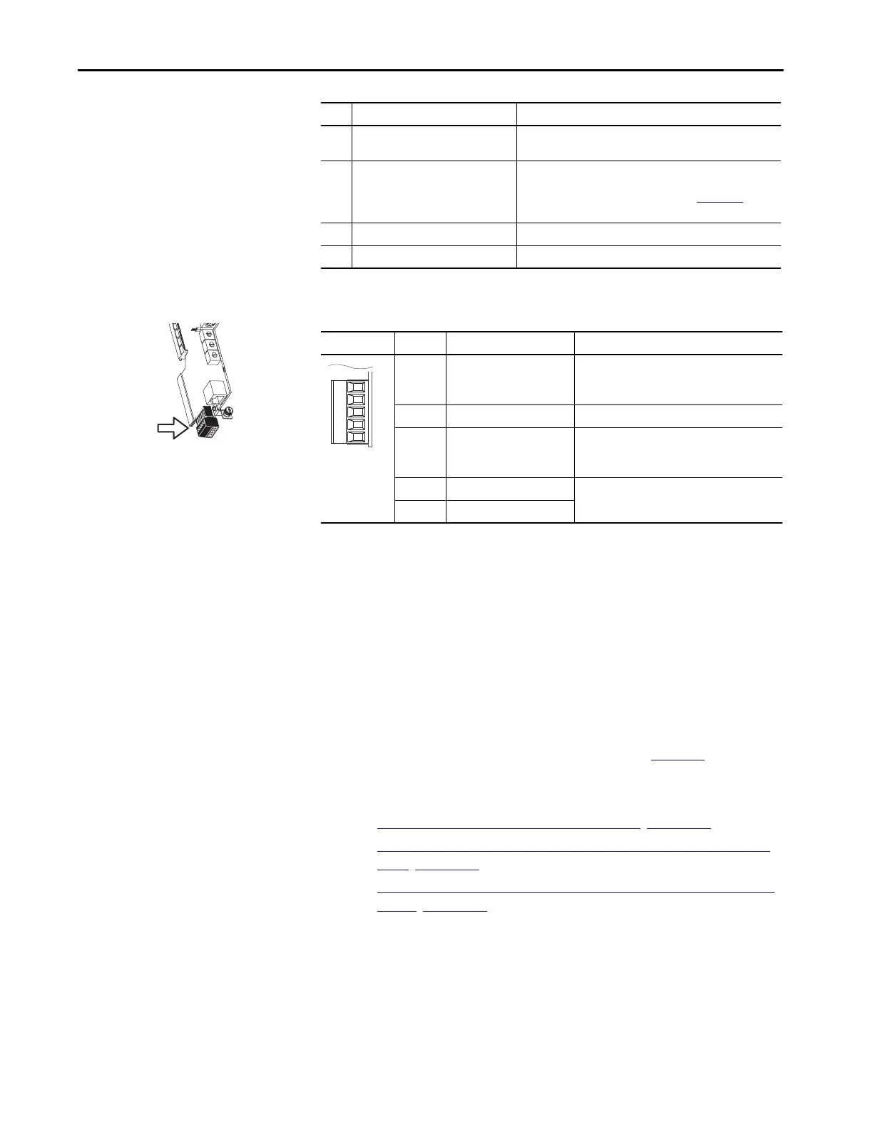
2. Locate and remove ENABLE jumper on the Main Control Board (see
the figure for your drive):
• PowerFlex 753 – ENABLE Jumper Location
, Figure 128
• PowerFlex 755 – ENABLE Jumper Location (Wall Mount Frames
1…7), Figure 129
• PowerFlex 755 – ENABLE Jumper Location (Floor Mount Frames
8…10), Figure 130
5 ENABLE jumper Hardware enable jumper. Removed when a hardware enable
configuration is used.
6 Embedded EtherNet/IP
(1)
address
selectors
Rotary switches for setting lowest octet of EtherNet address
(forces address to 192.168.1.xxx). See the PowerFlex 750-Series
AC Drives Programming Manual, publication 750-PM001
, for
instructions on setting the IP address.
7 Embedded EtherNet/IP
(1)
connector Network cable connection.
8 TB1 I/O terminal block.
(1) See the PowerFlex 755 Drive Embedded EtherNet/IP Adapter User Manual, publication 750COM-UM001.
No. Name Description
Fixed I/O Terminal Name Description
Di 0ac Digital input 0
120V AC (132V AC max)
Connections for AC power supply.
High state: 100…132V AC
Low state: 0…30V AC
Di C Digital input common Digital input common
Di 0dc Digital input 0
24V DC (30V DC max)
Connections for DC power supply.
High state: 20…24V DC
Low state: 0…5V DC
+24V +24V power Connections for drive supplied 24V power. 150 m
(492.1 ft) A max
24VC 24V common
 Loading...

