Rockwell Automation Publication 750-IN001P-EN-P - April 2017 161
Power Wiring Chapter 4
Wall Mount Frames 5…7
Common DC Input Terminal
Locations
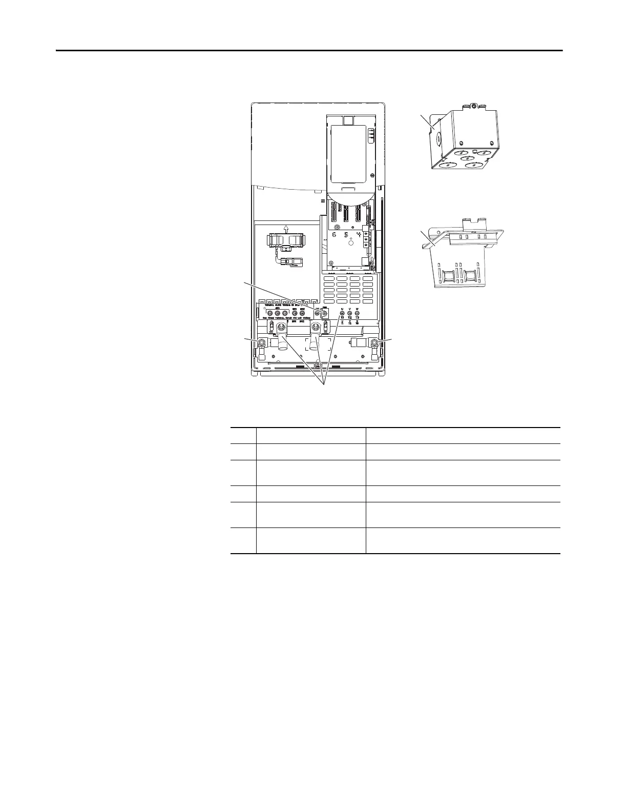
Figure 96 - Wall Mount Frame 5 Common DC Input Power Terminal and Termination Point
Locations
No. Name Description
1 Power terminal connections +DC, -DC, U/T1, V/T2, W/T3
2 PE grounding studs Terminating point to chassis ground for incoming DC line and
motor shields.
3 PE-B CMC jumper screw
4 Optional NEMA/UL Type 1 conduit
box
Terminating point to chassis ground for incoming AC line, motor
shields, and control wire shields.
5 Optional EMC plate Terminating point to chassis ground for incoming AC line, motor
shields, and control wire shields.
1
2
2
3
5
4
 Loading...

