162 Rockwell Automation Publication 750-IN001P-EN-P - April 2017
Chapter 4 Power Wiring
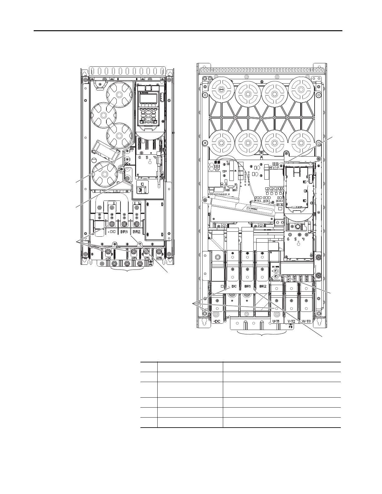
Figure 97 - Wall Mount Frames 6 and 7 Common DC Input Power Terminal and Termination
Point Locations
Wall Mount Frame 6
Wall Mount Frame 7
No. Name Description
1 Power terminals +DC, -DC, U/T1, V/T2, W/T3
2 PE grounding studs Terminating point to chassis ground for incoming DC line and
motor shield.
3 DC Bus and brake terminals +DC, -DC, BR1, BR2
4PE-B CMC jumper wire
5 DC+ and DC- Bus voltage test points
 Loading...

