Rockwell Automation Publication 750-IN001P-EN-P - April 2017 137
Lift and Mount the Drive Chapter 3
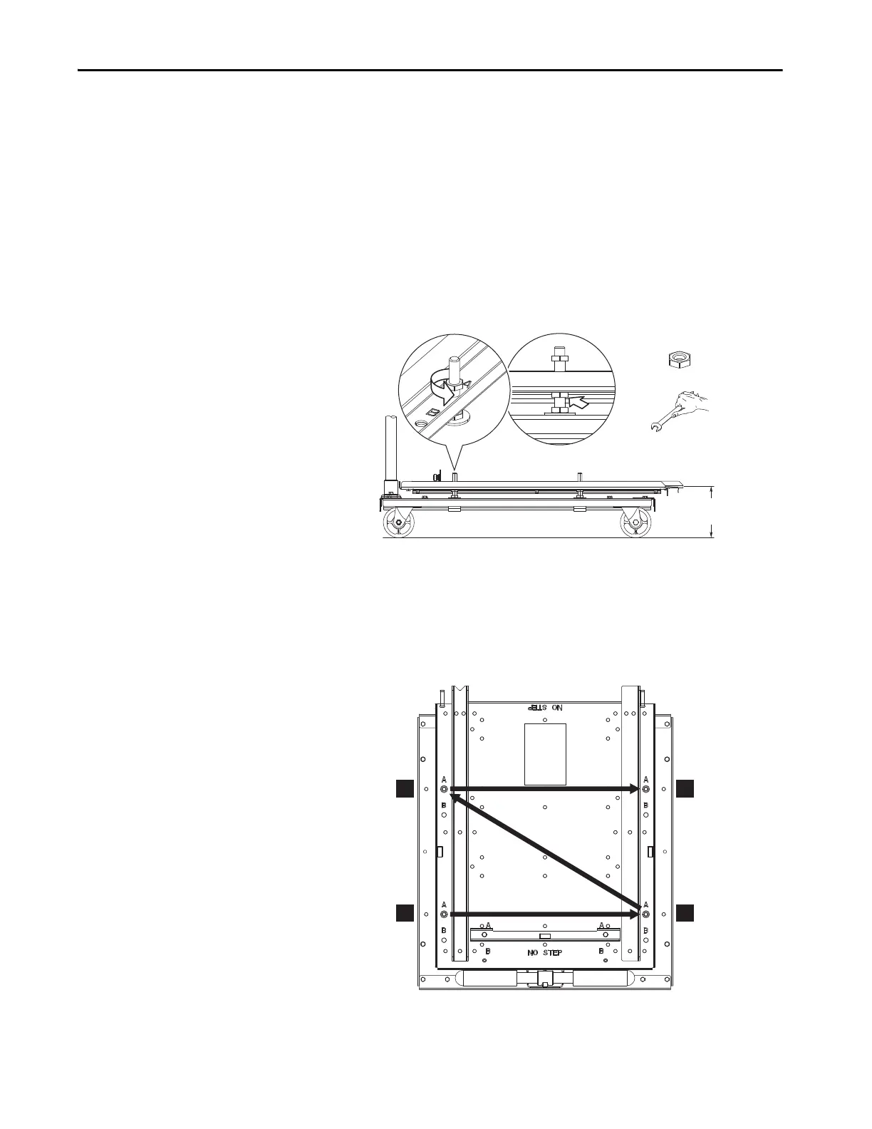
Adjust Roll-out Cart Height Using Threaded Studs and Nuts
The height of the roll-out cart deck can be adjusted using the threaded leveling
studs and nuts:
• Maximum height = 155.5 mm (6.1 in.)
• Minimum height = 116 mm (4.6 in.)
• Adjustment range = 30 m (98.4 ft)m (1.2 in.) up, 9.5 mm (0.4 in.) down
from the factory setting of 125.5 mm (4.9 in.)
1. Loosen and back off the top nuts on the four threaded level studs (see
number 1).
2. Turn the bottom supporting nuts to raise or lower the cart deck (see
number 2). Turn the nut clockwise to lower the deck. Turn the nut
counter-clockwise to raise the deck.
Make uniform half-turn adjustments to each of the four threaded studs
in an alternating pattern to help prevent binding and maintain a level
orientation.
3. To verify that the deck is level, use the three bubble levels.
4. Tighten the top nuts.
125.5 +30.0/-9.5
(4.9 +1.2/-0.4)
M10 x 1.5
17 mm
1
2
1
3
2
4
 Loading...

