Rockwell Automation Publication 750-IN001P-EN-P - April 2017 305
I/O Wiring Chapter 5
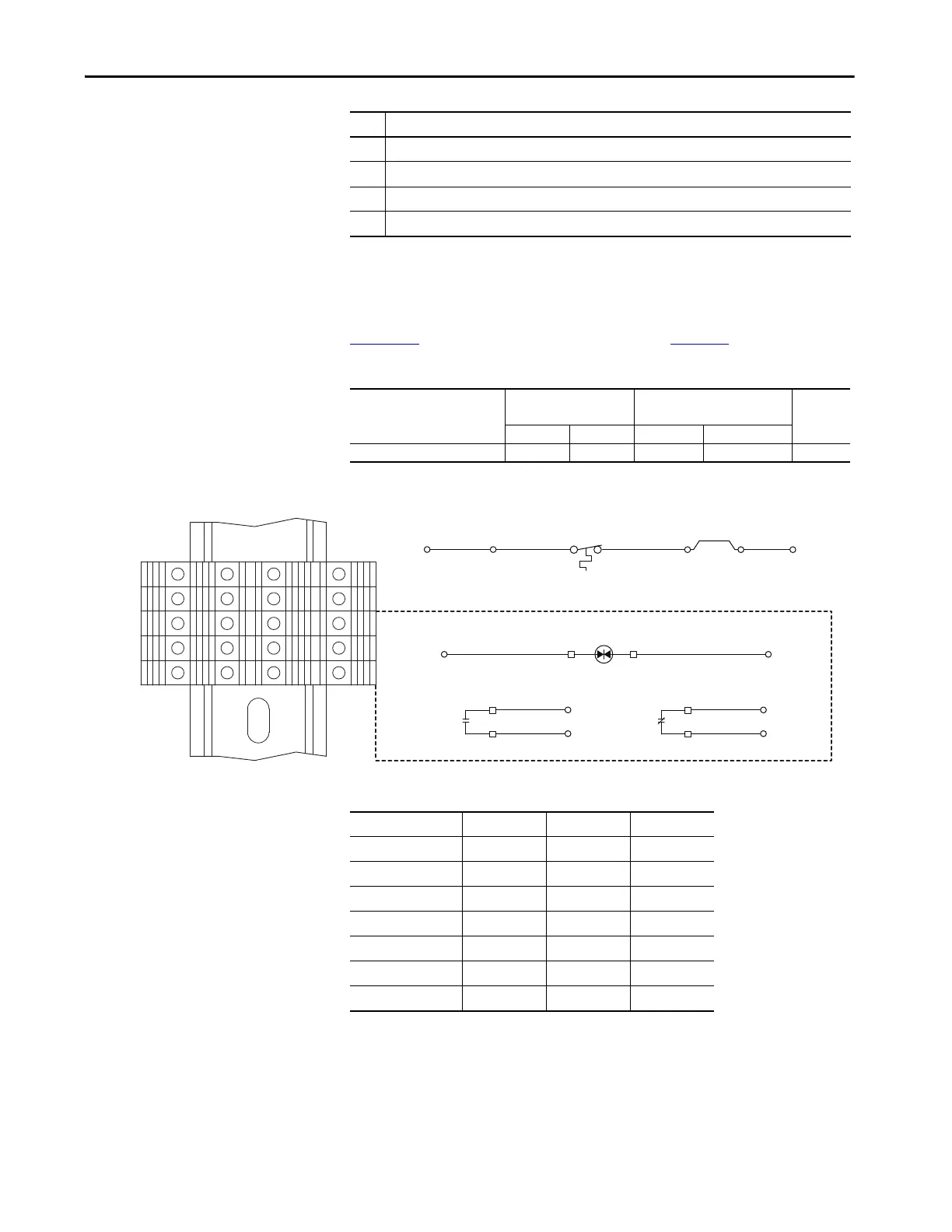
Control Wiring – Early Frame
8 Drives with Cabinet Options
Control terminal block TB2 is mounted on the inside right panel of the
cabinet options bay on early production frame 8 drives. TB1 referenced in
Figure 164
resides on the main control board. See page 236.
Table 119 - TB2 Terminal Block Specifications
Figure 164 - Control Terminal Block TB2 - Floor Mount Frame 8 Drives
Table 120 - Input/Output Contactor Data
5 Fan outlet. Keep clear to help maintain proper cooling.
6 Control cable entry and routing.
7 Human Interface Module (HIM) cable entry and routing.
8 Shield termination points.
No. Description
Name Wire Size Range
mm
2
(AWG)
Torque
N•m (lb•in)
Strip
Length
mm (in.)
Max Min Max Recommended
Control Terminal Block TB2 4.0 (12) 0.5 (20) 0.5 (4.5) 0.4 (3.5) 8 (0.32)
6
7
8
9
10
6
7
8
9
10
1
2
3
4
5
1
2
3
4
5
Input/Output Contactor
M2/M4
TB2(8)
TS1
Thermostat
TB2
W1
Hardware Enable Jumper
Note: Remove W1 jumper to
connect a hardware enable circuit.
TB2(7)TB2(6)
TB1(Di 0dc)
TB2(1)
TB1(+24V)
A1 A2
13
14
TB2(9)
TB2(4)
M2/M4
21
22
TB2(5)
TB2(10)
M2/M4
TB2(3)
Optional Devices
Cat. No.
(1)
(1) For full contactor specifications, see publications 100D-SG001 and 100G-SG001.
Input Pick-up Hold-in
100-D420EA11 50 Hz 490VA 18VA
100-D420ED11 60 Hz 490VA 18VA
100-D630EA11 50 Hz 1915VA 33VA
100-D630ED11 60 Hz 1915VA 33VA
100-D860EA11 50 Hz 1915VA 33VA
100-D860ED11 60 Hz 1915VA 33VA
100-G1200KD12 60 Hz 2,400VA 70VA
 Loading...

