Rockwell Automation Publication 750-IN001P-EN-P - April 2017 233
I/O Wiring Chapter 5
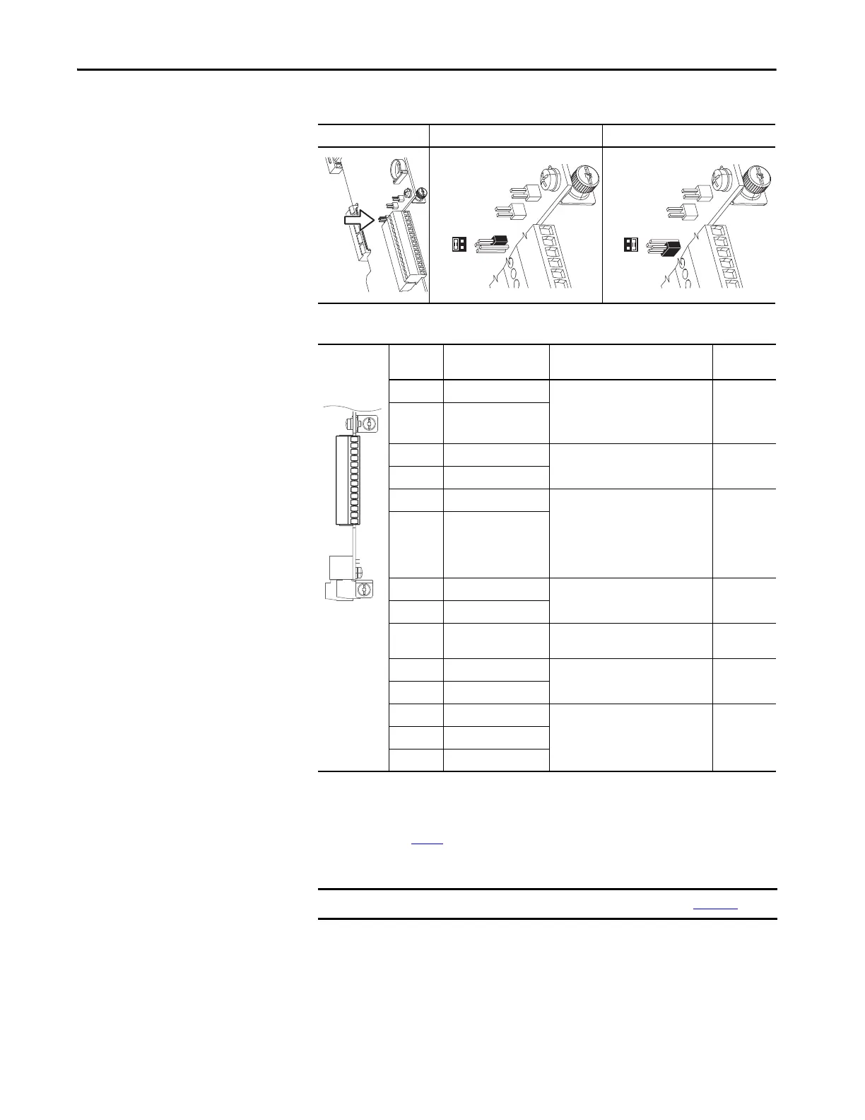
Table 53 - J4 Input Mode Jumper
Table 54 - TB1 Terminal Designations
Jumper Position Voltage Mode Current Mode
Terminal Name Description Related
Parameter
Ao0– Analog out 0 (–) Bipolar, ±10V
(1)
, 11 bit and sign, 2 kΩ
min load.
4…20 mA
(1)
, 11 bit and sign, 400 Ω
max load.
(1) Mode is selected only by parameter.
270
Ao0+ Analog out 0 (+)
10VC 10V common For (+) 10V references.
2 kΩ min.
+10V +10V reference
Ai0– Analog input 0 (–) Isolated
(2)
, bipolar, differential, 11 bit
and sign.
Voltage Mode:
(3)
±10V at 88 kΩ input
impedance.
Current Mode:
(3)
0…20 mA at 93 Ω
input impedance
(2) Differential Isolation – External source must be maintained at less than 160V regarding PE. Input provides high common mode
immunity.
(3) Mode is selected by jumper J4.
255
Ai0+ Analog input 0 (+)
Ptc– Motor PTC (–) Motor protection device
(Positive Temperature Coefficient).
(4)
(4) See HW Input PTC on page 250 for PTC data.
250
Ptc+ Motor PTC (+)
T0 Transistor output 0 Open drain output, 48V DC, 250 m (164
ft) A max load.
24VC 24V common Drive supplied logic input power.
150 m (492.1 ft) A max
+24V +24V DC
Di C Digital input common 24V DC (30V DC max) – Opto isolated
High state: 20…24V DC
Low state: 0…5V DC
220
Di 1 Digital input 1
Di 2 Digital input 2
IMPORTANT 753 Main Control Board I/O TB1 wiring examples begin on page 249.
J4
3 1
4 2
J4
3 1
4 2
Ao0-
Ao0+
10VC
+10V
Ai0-
Ai0+
Ptc-
Ptc+
To0
24VC
+24V
Di C
Di 1
Di 2
 Loading...

