Rockwell Automation Publication 750-IN001P-EN-P - April 2017 191
Power Wiring Chapter 4
750 kW 9 765 Normal 20G…F765 842 1170 721 900 1000 900 450 1600 900 450 2200 2200 900 842 1000
800 kW 9 795 Heavy 20G…F960 1193 1440 749 900 1000 950 475 1700 950 475 2200 2200 950 875 1000
795 Normal 20G…F795 875 1350 749 900 1000 950 475 1700 950 475 2200 2200 950 875 1000
790 Light 20G…F710 869 – 744 900 1000 950 475 1700 950 475 2200 2200 950 869 1000
850 kW 9
860 Light 20G…F765 946 – 810 900 1000 1000 500 1800 1000 500 2400 2400 1000 946 1000
900 kW 9 960 Normal 20G…F960 1056 1440 904 900 1000 1150 575 2000 1150 575 2700 2700 1150 1056 1000
960 Light 20G…F795 1056 – 904 900 1000 1150 575 2000 1150 575 2700 2700 1150 1056 1000
10 865 Heavy 20G…F1K0 1298 1560 815 900 1000 1000 500 1800 1000 500 2400 2400 1000 952 1000
1000 kW 9
1020 Light 20G…F795 1122 – 904 900 1000 1200 600 2200 1200 600 2900 2900 1200 1056 1000
10 1040 Normal 20G…F1K0 1144 1560 980 900 1000 1250 625 2200 1250 625 2900 2900 1250 1144 1000
1100 kW 10
1150 Light 20G…F1K0 1265 1380 1083 900 1000 1350 675 2400 1350 675 3200 3200 1350 1265 1000
1120 kW 10 1160 Heavy 20G…F1K4 1740 2100 1093 900 1000 1350 675 2500 1350 675 3300 3300 1350 1276 1000
1400 kW 10
1400 Normal 20G…F1K4 1540 2100 1319 900 1000 1650 825 3000 1650 825 4000 4000 1650 1540 1000
1500 kW 10 1485 Light 20G…F1K4 1634 1782 1399 900 1000 1750 875 3100 1750 875 4200 4200 1750 1634 1000
(1) “Applied Rating” refers to the motor that will be connected to the drive. For example, a “F400” drive can be used in Normal Duty mode on a 400 kW motor, in Heavy-duty mode on a 355 kW motor or in Light-duty mode on a 450 kW motor. The drive can be programmed
for each mode. Wiring and fuses can be sized based on the programmed mode. For any given drive catalog number, Normal Duty mode provides higher continuous current but smaller overload current when compared to Heavy-duty mode. See parameter 306 [Duty
Rating]. See Specifications for an explanation of Duty Ratings.
(2) These AC line fuses (with blown fuse indicators) are included in the drive to provide drive short circuit protection. AC input protection devices for branch circuit protection based on US NEC are listed in the table. Each drive bay has one fuse per phase.
(3) Minimum protection device size is the lowest rated device that supplies maximum protection without nuisance tripping.
(4) Maximum protection device size is the highest rated device that supplies drive protection. For US NEC, minimum size is 125% of motor FLA. Ratings that are shown are maximum.
(5) Circuit Breaker – inverse time breaker. For US NEC, minimum size is 125% of motor FLA. Ratings that are shown are maximum.
(6) Recommended Motor circuit protector – Instantaneous trip circuit breaker. Set the trip setting to the input current of the drive and size for the continuous current of the system.
(7) These DC line fuses (with blown fuse indicators) are included in the drive to provide drive short circuit protection.
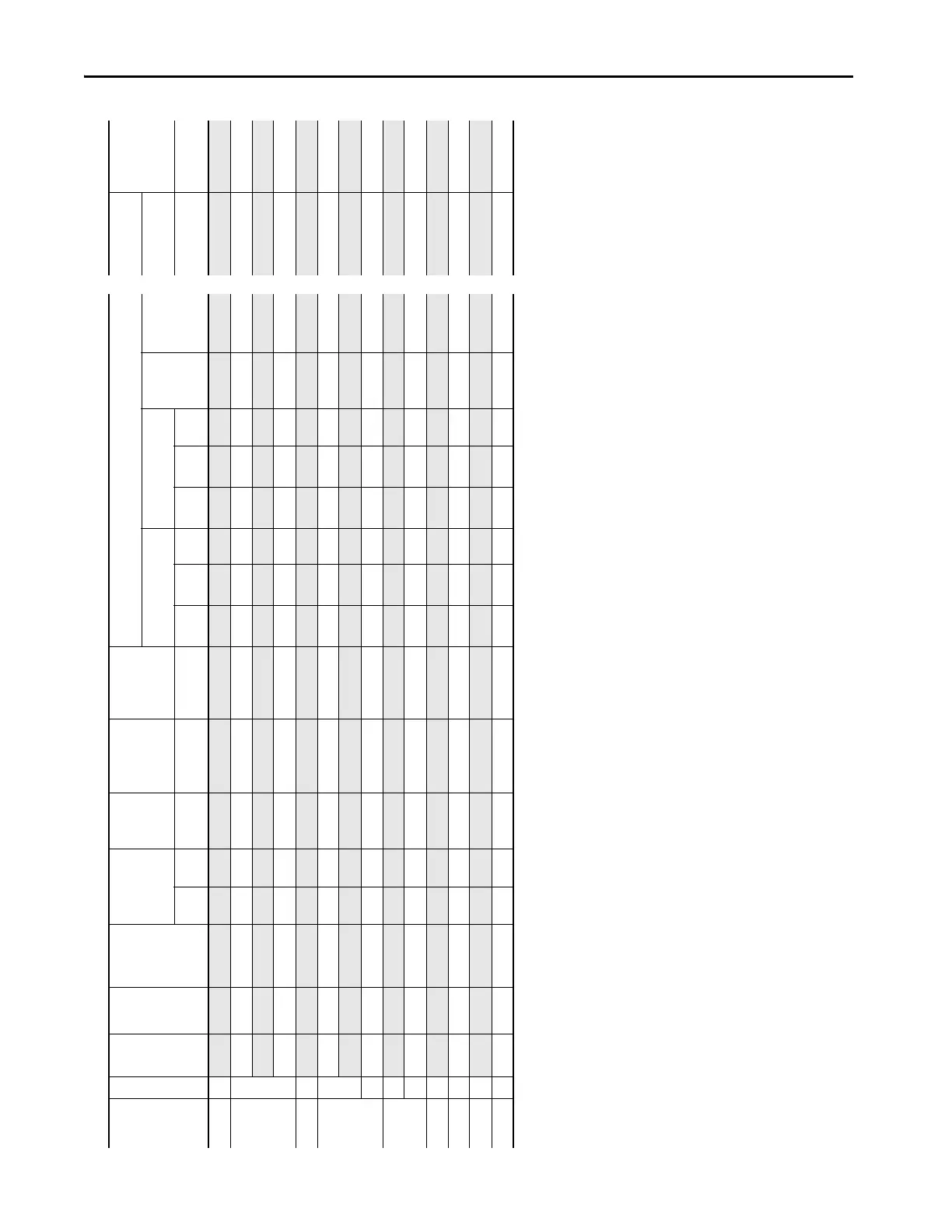
Table 26 - 690 Volt AC and 932 Volt DC Input Protection Devices – Floor Mount Frames 8…10 (Continued)
Applied
Rating
(1)
Frame
Cont.
Output
Amps
Duty Catalog
Number
Output Overload
Amps
Continuous
AC Input
AC Input
Integral
Semiconductor
Fuse Size
(170M)
(2)
DC Bay to Bay
Integral
Semiconductor
Fuse Size
(170M6648)
AC Input Protection Devices Recommended for Branch Circuit Protection
(Does not apply to 21G Drives with Options)
Input Quantities DC Input
Integral
Semiconductor
Fuse Size
(170M6253)
(7)
Dual Element Time Delay
Fuse
Non-Time Delay Fuse Circuit
Breaker
Max Size
(5)
Motor
Circuit
Protector
(6)
Continuous DC
Input
1 min 3 sec Amps Amps Amps 1/Phase
Min
(3)
2/Phase
Min
(3)
Max
(4)
1/Phase
Min
(3)
2/Phase
Min
(3)
Max
(4)
Amps Amps
 Loading...

