302 Rockwell Automation Publication 750-IN001P-EN-P - April 2017
Chapter 5 I/O Wiring
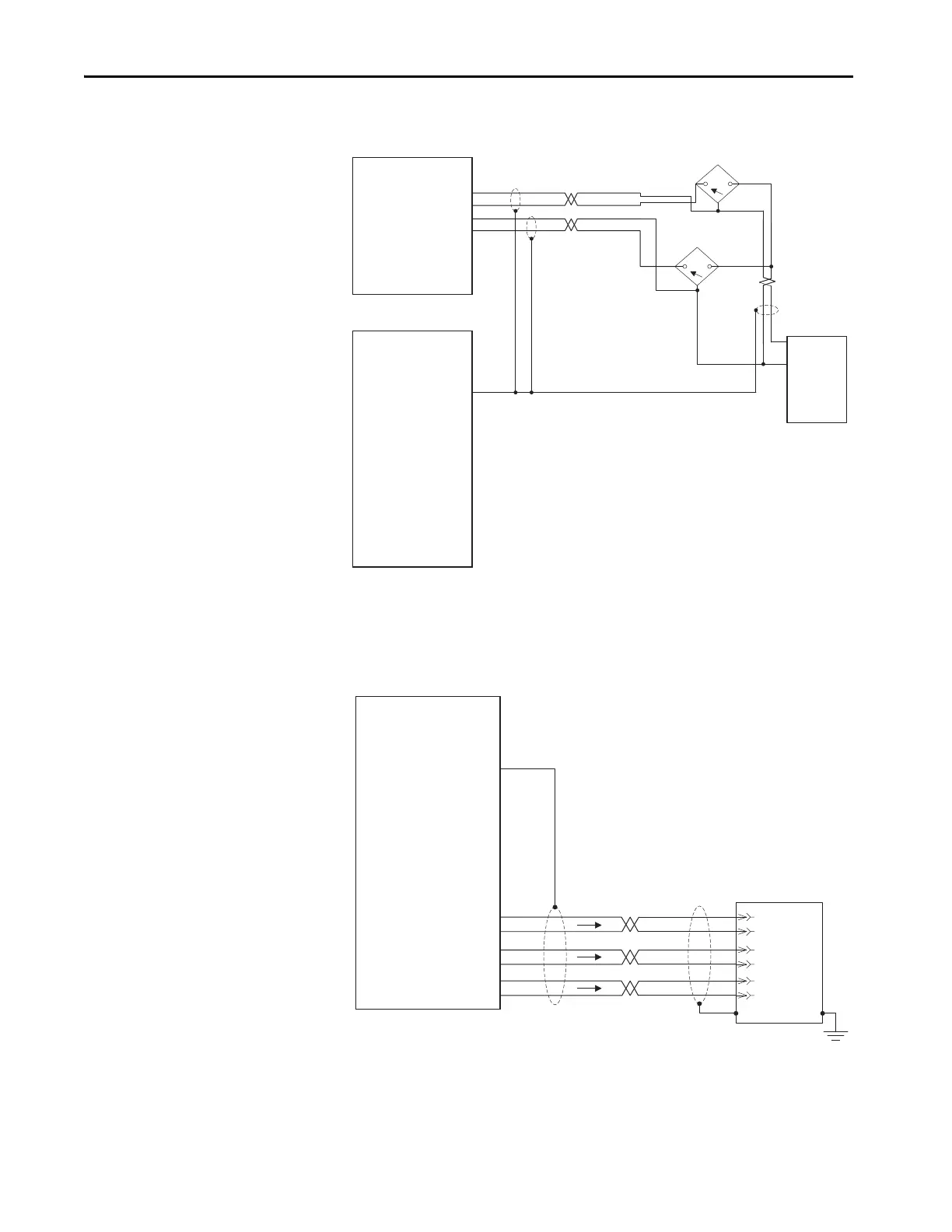
Figure 159 - Registration Sensor
See Universal Feedback parameters P90 through P129.
Figure 160 - Simulated Incremental Encoder Output
Set Universal Feedback parameter P80 [Enc Out Sel] to 2 “Sine Cosine,” 3
“Channel X,” or 4 “Channel Y” as needed.
Universal Feedback Option
Module TB1
Universal Feedback Option
Module TB2
-Hm
+Hm
-R0
+R0
-R1
+R1
-Yc
-Yd
+Yd
+Yc
Rotary Registration
Sensor
+ Power
Common
+ Power
Common
Line Registration
Sensor
Power
Common
External
Power
Supply
12 or 24V DC
-Sn
+Sn
-Cs
+Cs
IS
OS
-Xc
-Xd
+Xd
-Hf
+Hf
5c
+5
+Xc
12c
-A
A
-B
B
-Z
Z
+12
Universal Feedback Option
Module TB1
-Sn
+Sn
-Cs
+Cs
IS
OS
-Xc
-Xd
+Xd
-Hf
+Hf
5c
+5
+Xc
12c
+12
PE
Customer Equipment
-A
A
-B
B
-Z
Z
 Loading...

