Rockwell Automation Publication 1789-UM002K-EN-P - January 2015 91
Communicate with Serial Devices Chapter 4
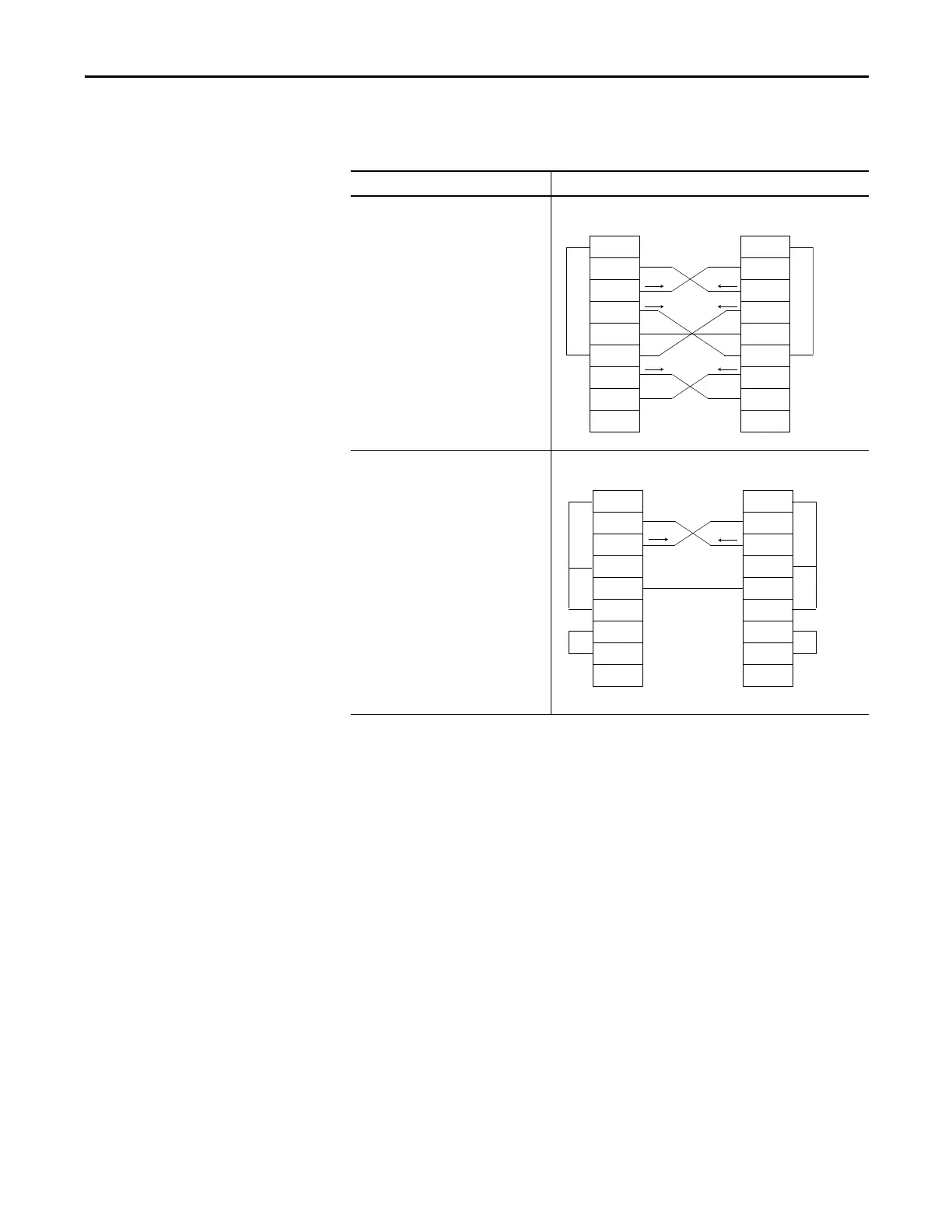
2. Connect the sending pins to the corresponding receiving pins and
attach jumpers.
3. Attach the cable shield to both connectors and tie the cable to
both connectors.
4. Connect the cable to the controller and the ASCII device.
User Mode Configuration
Complete these steps to specify ASCII protocol settings.
1. From the Edit menu, choose Controller Properties.
If the communication is Then wire the connectors as follows
Handshake
Do not handshake
2 RDX
3 TXD
4 DTR
COMMON
6 DSR
7 RTS
8 CTS
9
1 CD
2 RDX
3 TXD
4 DTR
COMMON
6 DSR
7 RTS
8 CTS
9
1 CD
ASCII Device Controller
42231
2 RDX
3 TXD
4 DTR
COMMON
6 DSR
7 RTS
8 CTS
9
1 CD
2 RDX
3 TXD
4 DTR
COMMON
6 DSR
7 RTS
8 CTS
9
1 CD
ASCII Device Controller
42232
 Loading...


