98 Rockwell Automation Publication 1789-UM002K-EN-P - January 2015
Chapter 5 Configure and Use Simulated I/O
3. Enter the module parameters.
4. Click OK.
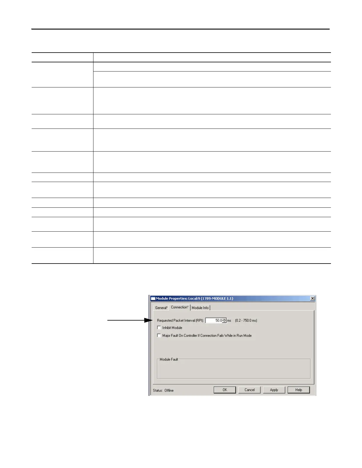
The Connection tab on the Module Properties dialog box opens.
Field Description
Type Read and Write - This connection lets the computer read inputs and write outputs.
Listen Only - This connection lets the controller read inputs, but not write outputs.
The Output Assembly Instance is the only field that is different from the Read and Write connection parameters.
Name Enter the name of the module.
The name must be IEC 1131-3 compliant. This is a required field and must be completed; otherwise you receive an error message when you exit
this tab. An error message is also displayed if a duplicate name is detected, or you enter an invalid character. If you exceed the maximum name
length allowed by the software, the extra characters are ignored.
Description Enter a description for the module here, up to 128 characters. You can use any printable character in this field. If you exceed the maximum
length, the software ignores any extra characters.
Comm Format Choose the communication format for the module. This field lists the available communication formats for the module.
When you choose a communication format, you are also defining the configuration formats for the module.
(Once you create a module, you cannot change the communication format. To change configuration, you must delete and recreate the module.)
Slot Enter the slot number where the module resides. The values range from 0…1 less than the chassis size (for example, if you have a 4-slot chassis,
the values are from 0…3). If you enter a slot number that is out of this range, you receive an error message when you go to apply your changes.
The slot number cannot be changed when online.
Input Assembly Instance Enter the input connection point for the primary connection. The default value is 1.
Output Assembly Instance Enter the output connection point for the primary connection. The default value is 2.
This parameter setting differs depending on whether the module Type is Read and Write or Listen Only.
Configuration Assembly Instance Enter the target of the connection. The default value is 4.
Configuration Size Enter the target of the connection. The default value is 4.
Status Input Instance Enter the size of the configuration assembly. The configuration data type associated with this module is a fixed size (400 bytes), but only the
amount of the data indicated by this parameter is sent as configuration data. The Size ranges from 0 to 400 bytes. The default value is 0 bytes.
Status Input Size Enter the size of the input assembly for the secondary connection. The default value is 1.
This field is disabled if you enter a value of 0, or if you leave it blank. It is hidden when the Comm Format does not indicate a status connection.
Status Output Instance Enter the output connection point for the secondary connection. The default value is 6.
This is field hidden when the Comm Format does not indicate a status connection.
 Loading...


