User Manual AMETEK Programmable Power
RS Series 106
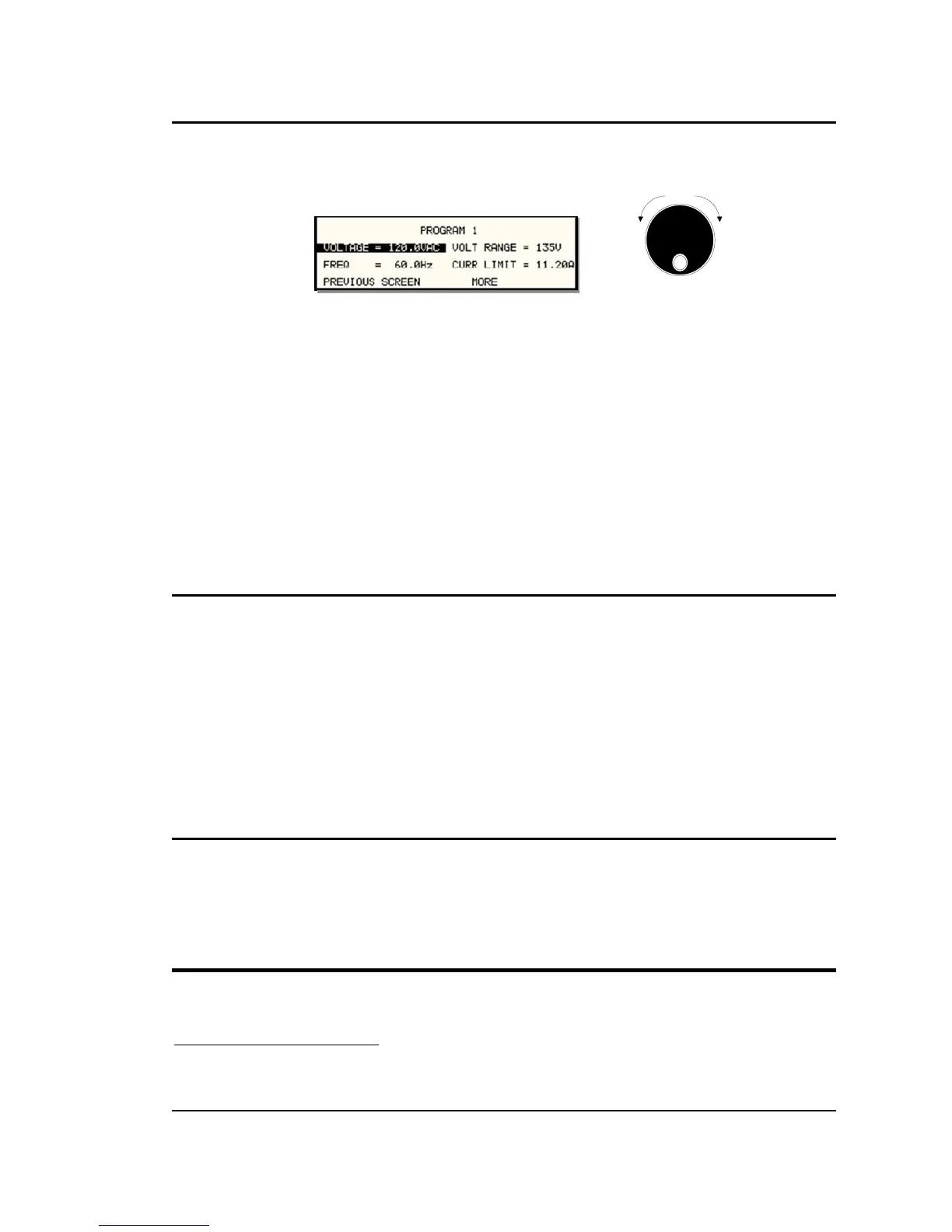
To change the output voltage:
Counter
Clock
wise
Clock
wise
INCRDECR
1. Press the SET key
2. Place the cursor on the VOLTAGE entry
3. Rotate the knob clockwise to increase the value, counterclockwise to decrease the value
4. The VOLTAGE field will be blinking to indicate a change in settings but the output remains
unchanged.
5. Place the cursor on the FREQ entry
6. Rotate the knob clockwise to increase the value, counterclockwise to decrease the value
7. The FREQ field will be blinking to indicate a change in settings but the output remains
unchanged.
8. Press the ENTER key.
Both new voltage and frequency output values are now present at the output. The unit has
returned to immediate mode of operation until the SET key is pressed again.
4.3.4 Change Output Values with the shuttle knob from the MEASUREMENT 1 screen
Basic output settings such as voltage and frequency can be changed from the MEAS 1 screen
by using the following procedure:
1. Select the PROGAM 1 screen by pressing the PROG key and position the cursor on either
the Voltage or Frequency setting field.
2. Select the MEASUREMENT 1 screen by pressing the MEAS key. A small arrow will be
showing in front of either the Voltage or Frequency measurement readout.
3. The shuttle knob can now be used to increment or decrement the selected parameter.
If three-phase mode is selected in the MEASUREMENT 1 screen, slewing the knob while the
voltage is selected will change the output voltage on all three phases. If only one phase is
selected, only the output of the selected phase will be affected.
4.3.5 Changing Voltage Output Modes
The RS Series supports AC mode, DC mode and AC+DC mode. The voltage mode can be
selected from the PROGRAM 2 screen, VOLT MODE field. The shuttle or +/- key will toggle
between available modes. It is recommended to set the initialization settings to the required
operating mode so the unit powers up in the correct voltage mode
1
. If not, the mode must be
selected before applying output power to prevent applying to wrong type of voltage.
4.4 Waveform Management
The RS Series with 3Pi controller employs independent arbitrary waveform generators for each
phase. This allows the user to create custom waveforms. In addition, three standard waveforms
1
If the mode is changed after power up and after the output relay is closed for the first time after power up, the measurement offset
calibration may not be correct. A phase mode change (-3Pi only) may be used to recalibrate the measurement offset.
 Loading...


