User Manual AMETEK Programmable Power
RS Series 38
Output Connections
3.5.1 Output Wiring
The output terminal blocks, TB1A and TB1B are located at the lower rear of the unit behind the
bottom access panel. See Figure 3-2 for details.
Three phase output line connections are made to terminal block TB1A. The phase outputs are
labeled A, B and C. The neutral connection (if needed) can be made on terminal block TB1B.
The neutral connection is always required to connect Y loads or for connecting a single phase
load to Phase A only.
The external sense inputs allow the power system output voltages to be monitored directly at the
load and must be connected at TB2 when the sense is programmed for external. The external
sense input does not have to be connected when Internal Sense is programmed. The external
sense wires are to be connected to TB2 on the rear panel and should be run using a twisted
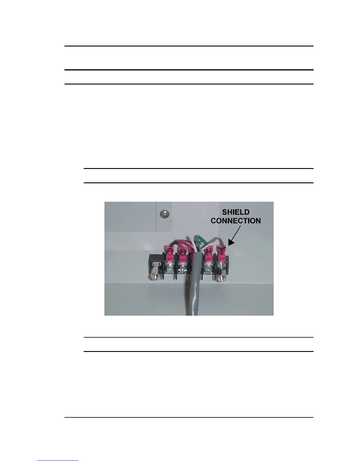
shielded cable. See Figure 3-4 for location of TB2 and Figure 3-5 for shield connection detail.
Note: For External Sense connection, a shielded cable MUST be used with the shield
connected to chassis ground at the Ext. Sense connector. (See Figure 3-5).
External sense is recommended for multi-cabinet systems is the output wiring from the cabinets
to the common output terminal block supplied is not of equal length.
Figure 3-5: External sense cable shield connection to chassis ground
Note: The output of the power source is isolated from the input line and floating with
respect to chassis ground. If needed, either side (HI or LO) may be grounded.
If the EUT changes frequently, you may want to consider using some quick disconnect scheme
external to the RS so it will not be necessary to power down the RS and remove the front
covers. This can take the form of a panel-mounted socket (1 or 3 phase) of sufficient current
and voltage rating. (Not supplied with RS)
The output power cables must be large enough to prevent a total voltage drop exceeding 1% of
the rated output voltage between the power source and the load. Table 3-2 shows the size of
the cables that may be used. Note that wires must be sized to accommodate the maximum

 Loading...


