User Manual AMETEK Programmable Power
RS Series 147
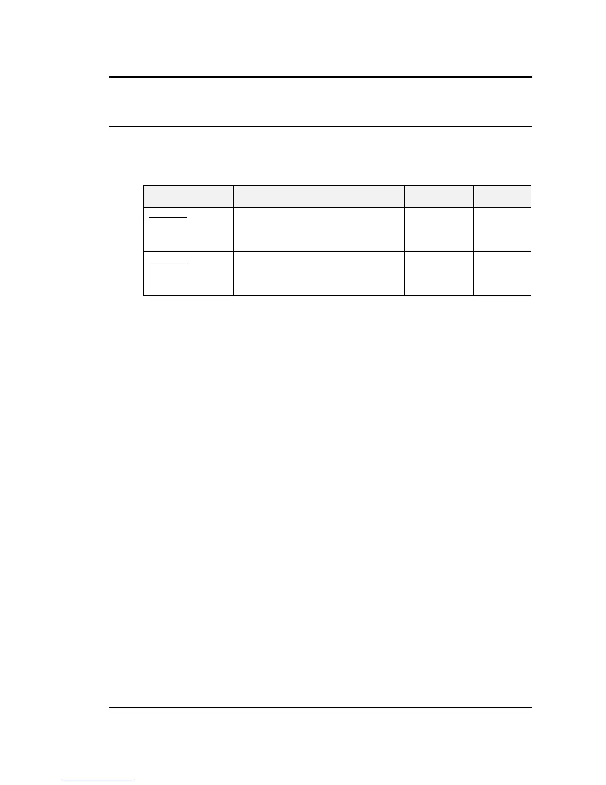
6.3.3 Measurement Calibration Summary
The following Table is a summary of the preceding calibration steps. The value indicated by the
External DVM is called V
AC
or V
DC
. The current measured by the current shunt is called I
AC
or
I
DC
.
TITLE PROGRAM/LOAD PARAMETERS PARAMETER ADJUST TO
AC MODE
AC Volt Full-scale 300 VAC Range, 240 VAC, 60 Hz, no load VOLT FS V
AC
AC Current Full-scale 150 VAC Range, 120 VAC, 60 Hz, full load
to 90% of max current range.
CURR FS I
AC
DC MODE
DC Volt + Full-scale 400 VDC Range, + 320 VDC, no load VOLT FS V
DC
DC Current Full-scale 200 VDC Range, 160 VDC, full load to 90%
of max. current range.
CURR FS I
DC
Table 6-2: Measurement Calibration Table - TBD
Repeat Paragraph 6.3 for each phase. Move the external test equipment to the phase that is
being calibrated. Refer to Figure 6-2..
While viewing the calibration screen, press the PHASE key to select the respective phase.
 Loading...


