User Manual AMETEK Programmable Power
RS Series 137
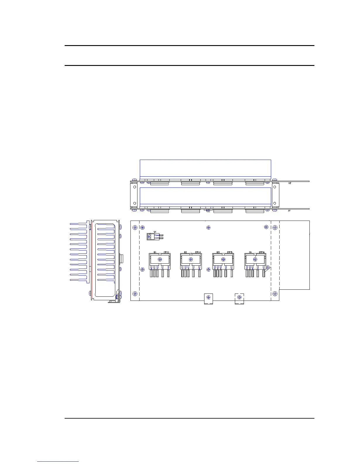
5.7.3 Amplifier Boards
The Amplifier boards are each attached to a heat sink and stacked on top of each other at the
top portion of the power module enclosure. Sets of two boards are held together by a bracket
which screws into the back wall of the power module enclosure. Power to each amplifier board
is supplied from the PFC section through a set of DC bus bars. Each amplifier board connects
to the modulator board via a small ribbon cable. Each Amplifier board has four outputs (A+. A-,
B+ and B-). These four outputs connect to a set of Inductor boards using stranded wires with
Anderson style connectors. The connection between the Amplifier boards and the Inductor
boards is specific and should not be reversed or damage could result. The output wire
connectors of each amplifier board are color coded to help identify the correct connections. The
connections between the Modulator board and the Amplifier boards are one to one. (Connectors
line up with amplifier boards).
The layout of the Amplifier board is shown in Figure 5-5.
Figure 5-5: Amplifier Board Layout
 Loading...


