User Manual AMETEK Programmable Power
RS Series 45
3.6 Connectors - Rear Panel
A number of connectors are located along the center rear panel. These connectors are in a
recessed area to protect them from shipment damage.
3.6.1 System Interface
WARNING: The system interface connectors are for use with AMETEK Programmable
Power supplied cables, and only between California Instruments equipment.
The Clock and Lock BNC connectors located on the rear panel are used to synchronize and
control the phase shift between the three outputs when 3 units are operating as a three-phase
clock and lock system. This mode of operation requires the -LKM (on Master unit) and -LKS (on
Auxiliary units) options. See paragraph 3.9 for more information on this mode of operation.
A set of two identical System Interface connectors, P8 and P9 ( TBD ) is located on the rear
panel of each RS chassis. The system interface is used to connect the multiple RS90 power
sources in a Master/Auxiliary configuration to create RS180 through RS540 models. In these
configurations, only the Master RS90 power source has a built-in controller and front panel
unless the Multi-box option (-MB) was specified at the of order. On –MB systems, two or more
than RS90 chassis has a controller allowing reconfiguration into smaller power systems.
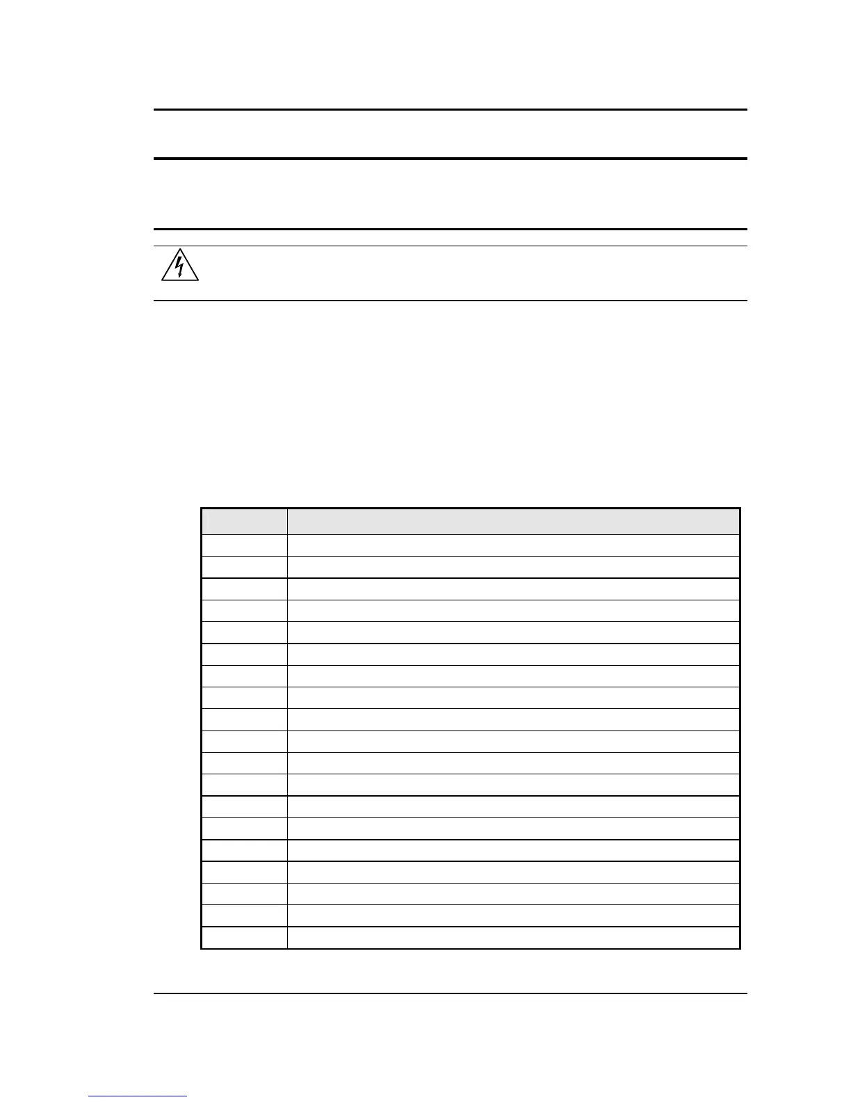
The same connector is also used to control the optional OMNI-3-75 Reference Impedance.
P8 / P9 Description
1 OUTP: Output ON. Controls state of output relay
2 N/C
3 N/C
4 N/C
5 COM: Common. Signal return.
6 OT: Over temperature. Indicates over temperature condition.
7 N/C
8 CLB: Current Limit B. Programmed current limit reference for phase B
9 CSA: Current Sum Phase A
10 CSC: Current Sum Phase C
11 FLT A: Amplifier Fault Phase A
12 FLT C: Amplifier Fault Phase C
13 XFMR: Optional voltage range select. (-HV or -XV option)
14 PARALLEL: Parallel operation control.
15 INPUT ON: Input power status
16 A ERR LO: Error Signal Phase A, low
17 B ERR HI: Error Signal Phase B, high
18 N/C
19 C ERR LO: Error Signal Phase C, Low
 Loading...


