User Manual AMETEK Programmable Power
RS Series 82
4.2.6.2 VOLTAGE SWEEP/STEP sub menu
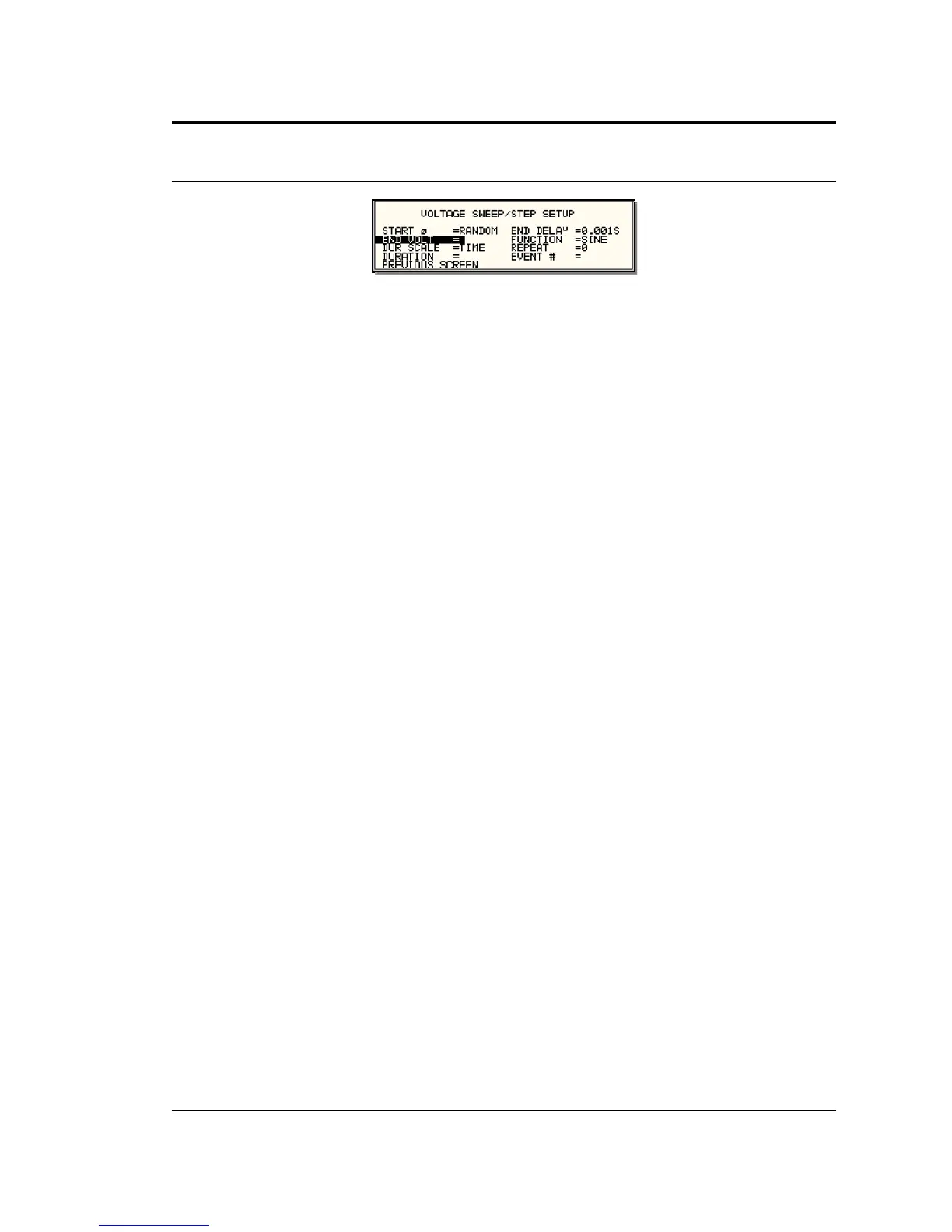
Figure 4-13: VOLTAGE SWEEP/STEP SETUP Screen
The Voltage sweep and step screen shown in Figure 4-13 can be reached from the transient
screen as follows:
1. Scroll to the VOLT SWEEP/STEP entry using the up and down keys.
2. Press the ENTER key to bring up the VOLTAGE SWEEP/STEP screen.
The VOLTAGE SWEEP/STEP screen has several data fields. All data fields that are blank to the
right of the equal sign must be filled or an error message will occur when trying to leave this
screen. The EVENT # is the last data field to be filled. Entering the event data field will cause the
display to return to the TRANSIENT screen where a new selection can be made.
The VOLTAGE SWEEP/STEP screen has the following fields:
START This field will show the start phase angle of the voltage transient
in degrees. Only one start phase angle per transient sequence
is allowed. The start phase angle must be in the first transient
event in the list. The start phase angle is not valid for DC
transient.
END VOLT This is the output voltage level at the end of the transient event
in volts.
DUR SCALE Duration scale default is time in seconds. Use the Shuttle knob
to select CYCLES if desired. Note that durations expressed in
cycles may cause rounding errors if the period of the selected
frequency setting is not an integer number of mss. Thus, for 50
Hz applications, no rounding errors occur but for 60 Hz, the
16.66¯ ms period will cause a rounding error when converted.
The Duration scale selection affects both the DURATION and
END DELAY parameters.
DURATION Duration is the time it will take for the output voltage to reach
the END VOLT level. As such, “Duration” will define the slew
rate of the output voltage for the event. A duration of 0 seconds
will cause the output voltage to reach the end voltage
immediately. The DUR SCALE defines the time parameter
CYCLES or SECONDS
END DELAY This is the time delay the voltage level will stay at END VOLT
before it proceeds with the next transient event or completes
the transient.
FUNCTION This field can be used to select the wave shape to be used
during this step of the transient sequence. Each step can use a
different wave shape from the available library of 50 user-
defined waveforms or the three standard waveforms. The
output wave shape changes upon entry into each step and
remains in effect for the duration of the step. The default wave
shape is always the SINE (sine wave).
 Loading...


