User Manual AMETEK Programmable Power
RS Series 184
the normally programmed phase angle relationship. For firmware upgrades, contact
service.ppd@ametek.com.
Note that required phase angles and amplitudes are automatically set for dips of 0, 40, 70, 80
and 100% to conform with method (A). For all other dip levels, method (A) can be used by
programming the required phase angles to be used during the programmed dips. The amplitude
and phase angles required to obtain the correct line-to-line voltage dip per method (A) for
standard dip levels of 40, 70 and 80% are embedded in the firmware and conform to table C.2 of
IEC 61000-4-34.
Since all phase programming on the RS series is referenced to phase A, voltage dip with a
phase angle for A other than 0° are implemented by offsetting all three phases by the required
number of degrees to get phase A at 0°. This is reflected in the actual output settings shown on
the RS versus the data in table C.2 of the IEC61000-4-34. The actual output settings are shown
in the last 3 columns.
Phase Mapping
The phase rotation on the RS series is ACB. This means phase A is mapped to L1, phase B is
mapped to L3 and phase C is mapped to L2. The required phase selection letter combination
for the required Line-to-line dip is shown in table C.2 for reference.
L1 A
L2 C
L3 B
Table 9-17: Phase mapping
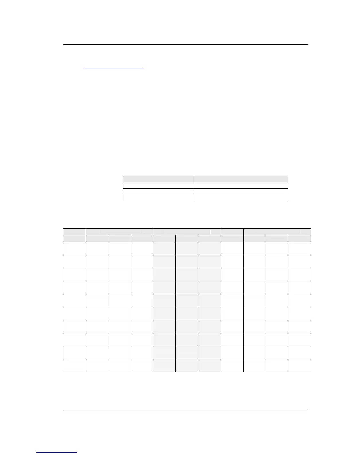
To select the desired phase-to-phase dip, select the phase selection as shown in column 8 and
either 80, 70 or 40 % dip level from the IEC411 screen or the Gui. Table C.2
Line to Line Line to Neutral Phase RS Setting
L1-L2 L2-L3 L3-L1 L1-N L2-N L3-N Selection

 Loading...


