User Manual AMETEK Programmable Power
RS Series 40
Output Terminal Blocks
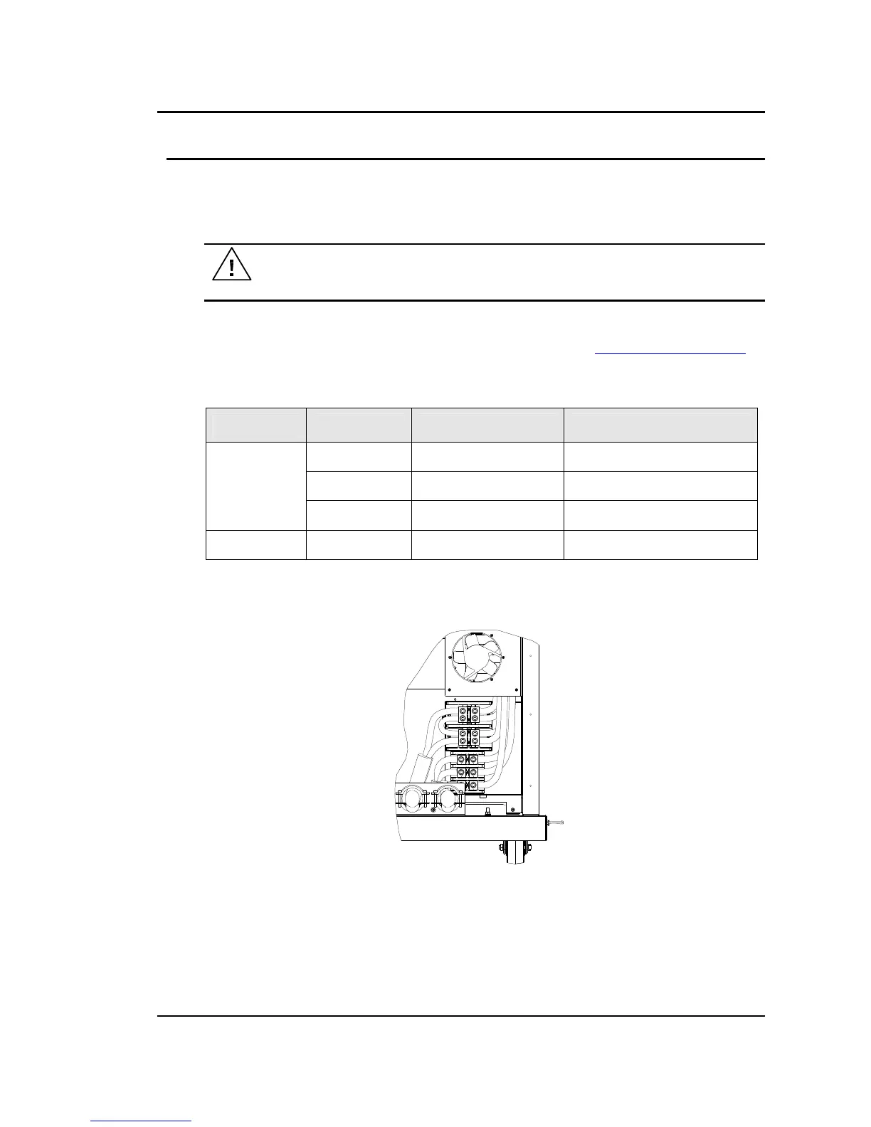
The RS90 has two output terminal blocks, TB1A and TB1B. The terminal blocks are large
enough to accommodate the recommended wire gauge sizes shown in Table 3-2. The terminal
blocks are located in the lower right corner on the back of the unit when facing the rear. The rear
access panel at the bottom of the chassis needs to be removed to access these terminal blocks.
CAUTION: REMOVE ALL INPUT POWER TO THE RS BEFORE REMOVING
THE REAR ACCESS PANEL.
The correct standard size Allen wrenches for connecting output wiring to TB1A and/or TB1B are
supplied with each RS in the ship kit. Look for a brown envelope. If the correct tools cannot be
found, contact AMETEK Programmable Power customer service at service.ppd@ametek.com.
Terminal block TB1B provides the output neutral connection of the three phase WYE output.
Phase A, B and C outputs are provided trough terminals 1, 2 and 3 of TB1A respectively.
Connector Terminal Mode Output
TB1A 1 3 Phase Phase A
2 3 Phase Phase B
3 3 Phase Phase C
TB1B 1 - 4 3 Phase Neutral
Table 3-3: Output Terminal connections.
TB1A
TB1B
CHASSIS
GND
Figure 3-6: Location of Output Terminals (Rear view)

 Loading...


