User Manual AMETEK Programmable Power
RS Series 47
3.6.3 BNC Connectors
BNC connectors. Functions are called out on rear panel decal. Table shows connections from
left to right when standing at the rear of the RS cabinet.
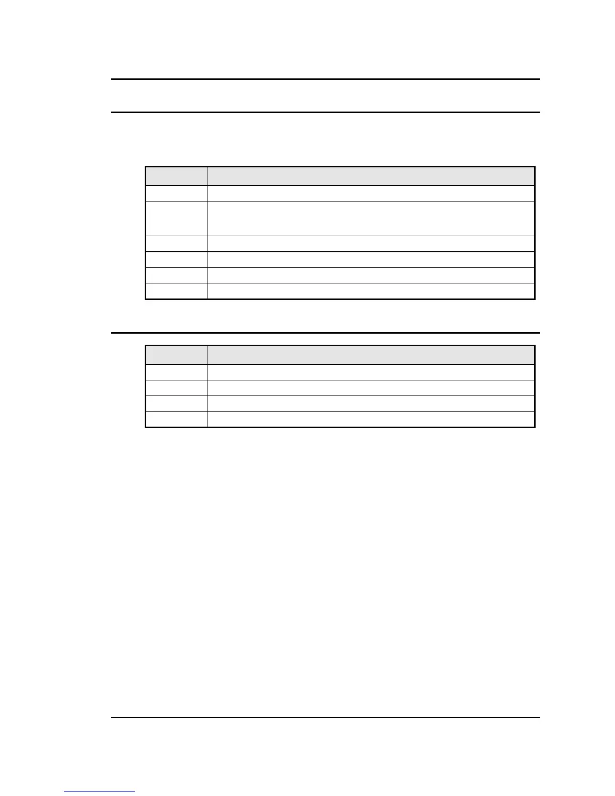
Table 3-6: BNC Connectors
BNC Description
1 Trigger Input (TTL input)
2 Trigger Output (TTL output) (Same signal connection as Function Strobe. Some units
may not have this output connected. If you don’t get an output trigger on this BNC, use
the Function Strobe BNC instead.)
3 Function Strobe (TTL output) (Same signal connection as Trigger Output)
4 Clock (TTL output on Master / TTL input on Auxiliary)
5 Lock (TTL output on Master / TTL input on Auxiliary)
6 Emergency Shut off inter connect. Installed only on –MB systems with –ES Option.
Table 3-7: BNC Connectors
3.6.4 External Sense Connector
Pin Description
1 Phase A sense
2 Phase B sense
3 Phase C sense
4 Neutral sense
Table 3-8: External Sense Connector

 Loading...


