User Manual AMETEK Programmable Power
RS Series 41
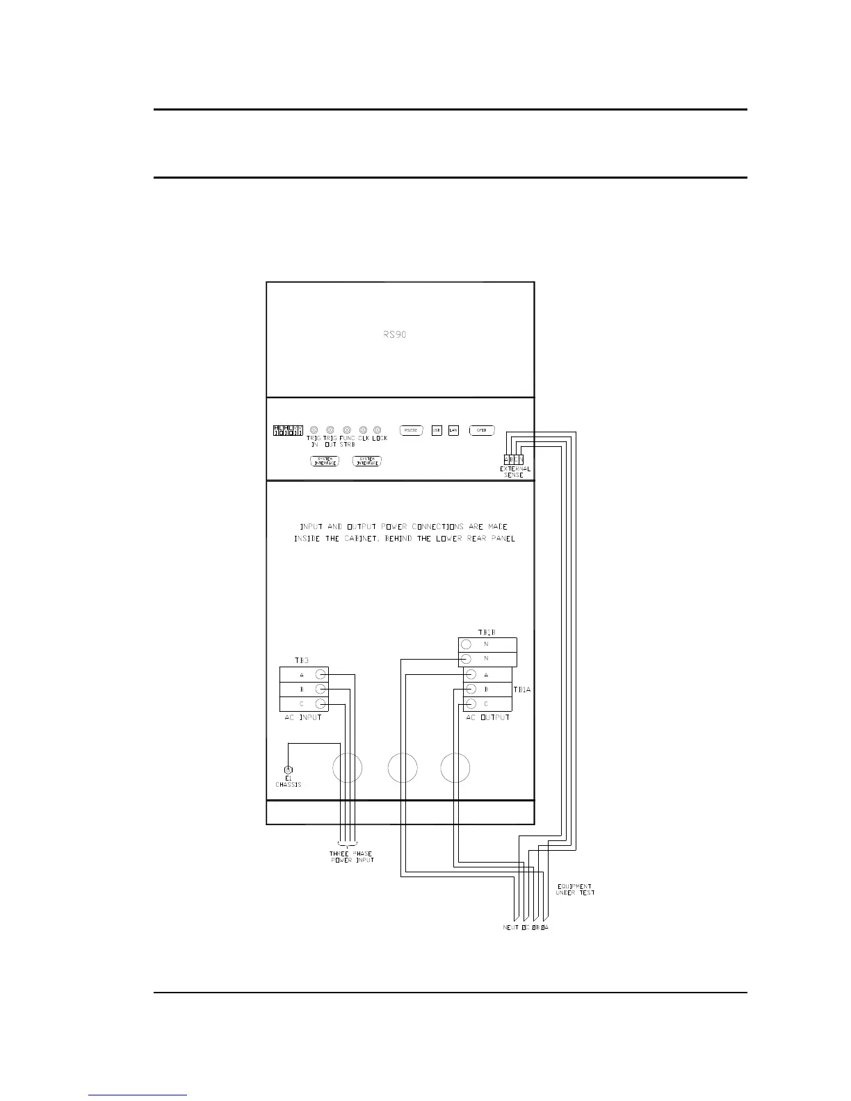
3.5.2 Output Wiring Diagram
Figure 3-7 shows the required output wiring connections for a RS90 (rear panel view).
Always disconnect all input power from the RS before removing the rear terminal block access
panel. Route the load wires through the strain relief clamps. Depending on wire size required, it
may be necessary to use two strain relief holes with 2 wires through each as shown.
Figure 3-7: RS90 Output Wiring (Rear panel view)
 Loading...


