User Manual AMETEK Programmable Power
RS Series 185
Other Dip levels for 2 phase selections.
Note that any other dip level not listed in this table will result in voltage dips conform method (B)
so both phases will dip by the actual dip percentage set.
To implement user defined three phase dips other than those listed in this table, the IEC411
phase setting for phases A, B and C may be used to set the desired phase angle for each dips.
This setting is ignored if the dip levels is set to 80, 70 or 40 but otherwise controls the phase
angle of the selected phase during the dip.
To set the phase angle for a voltage dip, select the individual phase using the PHASE key and
use the PHASE = field in the 411 screen to set the required phase angle. Note that this is not the
start phase angle for the dip but rather the phase offset with respect to phase A. (Requires FW
1.17 on Series I RS units or 4.17 on Series II RS units.
9.4.5 Tests Performed
9.4.5.1 DIPS AND INTERRUPTIONS
1. Run All
Run predefined sequence of tests.
2. Run Single
Run user defined test.
9.4.5.2 VOLTAGE VARIATIONS
1. Run All
Run predefined sequence of tests.
2. Run Single
Run user defined test.
9.4.6 Front Panel Entry
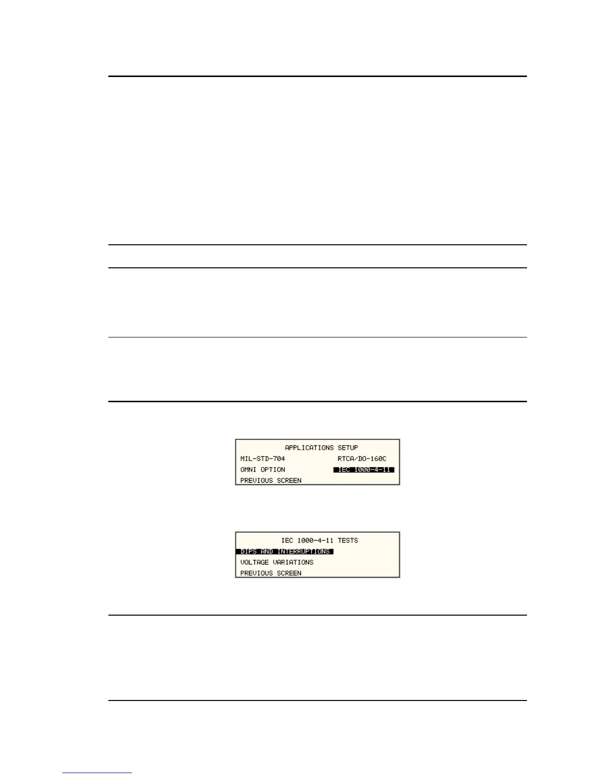
To perform a test from the keyboard, select the APPLICATIONS screen from the MENU 2
screen. The APPLICATIONS screen will appear as shown in Figure 9-13
Figure 9-13: Application Menu
Scroll to the IEC 1000-4-11 entry using the up and down cursor keys. Press the ENTER key to
select the IEC 1000-4-11 main menu. The screen will appear as shown in Figure 9-14.
Figure 9-14: IEC1000-4-11 Menu
9.4.6.1 DIPS AND INTERRUPTIONS TEST
Scroll to the DIPS AND INTERRUPTIONS entry using the up and down cursor keys. Press the
ENTER key to select the DIPS AND INTERRUPTIONS menu. The screen will appear as shown
in Figure 9-15.

 Loading...


