User Manual AMETEK Programmable Power
RS Series 36
The input power cables and protective circuit breaker used must be large enough to handle the
input current and input voltage of the power source and must conform to local electrical codes.
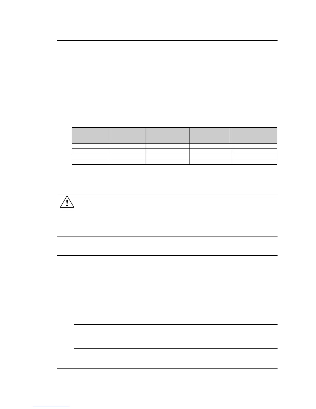
Consult a qualified electrician prior to installation. Table 3-1 shows the size of the cables that
may be used per RS cabinet. Note that wires must be sized to accommodate the worst-case
maximum current that may occur under low line conditions. Local electrical codes may also
require different wire types and sizes. These ratings should also be used when selecting a
circuit breaker or equivalent disconnect device.
Cable lengths must not exceed twenty-five (25) feet. For lengths greater than 25 feet, calculate
the voltage drop from the following formula:
2 X DISTANCE X CABLE RESISTANCE PER FT. X CURRENT = VOLT DROP
Table 3-1: Suggested Input Wiring Sizes for each RS Cabinet *
Nominal Line
Voltage
Load Current
@ low line
Wire Gauge (US) Circular Mils
(Kcmils)
Metric (mm2)
480 V 150 A
4/0 AWG 212.0 107.0
* Data shown for use of high temperature (100° C) rated stranded copper wire, unbundled and not
installed in conduit. Adjust wire gauge for Aluminum wire type. Always consult the National Electrical
Code and/or local code regulations for proper rating and size of wire cabling prior to installation.
CAUTION: Capacitors in the power source may hold a hazardous electrical charge
even if the power source has been disconnected from the mains supply. Allow
capacitors to discharge to a safe voltage before touching exposed pins of mains
supply connectors.
Power modules need at least 15 Minutes to discharge to safe levels before they can
be removed.
3.5 AC On/Off Circuit Breaker on RS Series front panel.
It is important to understand the purpose and operation of the On/Off circuit breaker of the RS
Series located on the lower left side of the front panel. This is a 2A rated breaker that is used to
engage and protect the two LV Power supplies of the RS chassis only. The LV Power supplies
provides DC bias power to the entire RS system. The AC input power is routed through a set of
three AC line fuses (F1, F2 and F3) located in the lower rear left bottom corner of the RS. (See
Figure 3-2 for fuse locations). These fuses protect the three RS amplifiers and the AC input
transformer from excessive input currents. The AC input power is connected to the input
transformer through a large three-pole contactor. Removing AC power to the LV Power Supply
by opening the front panel circuit breaker (moving the lever to the down (OFF) position) will
cause this contactor to loose its coil voltage and will result in it opening and disconnecting the
input transformer and amplifier from AC mains input.
Note: If any RS system failure has occurred on any part of the RS system, AC input
power must be removed immediately and not restored until the system has been
inspected by a qualifier service technician.
Always turn off the On/Off Circuit breaker before re-applying AC input power.

 Loading...


