User Manual AMETEK Programmable Power
RS Series 61
4. Front Panel Operation
4.1 Tour of the Front Panel
The RS Series with type non-Pi (basic) or type Pi controllers have identical front panels
although some of the keys found on the front panel are only used by RS models with the 3Pi
controller. If your unit is a P type controller, these keys will act as don’t cares. This chapter
provides information on operating the RS with either controller type.
Before operating the AC source using the front panel, it helps to understand the operation of the
front panel controls. Specifically, the operation of the knob, keyboard and the menu layout are
covered in the next few paragraphs.
4.1.1 Front Panel Controls and Indicators
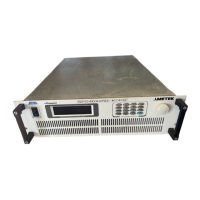
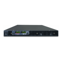
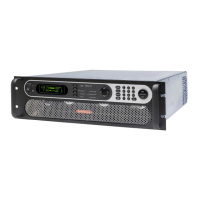
The front panel can be divided in a small number of functional areas:
• Mains circuit breaker
• Status Indicator lights
• Shuttle knob
• LCD display
• FUNCTION keypad
• DATA ENTRY keypad
4.1.2 System On/Off Circuit Breaker
The circuit breaker located on the bottom left side of the front panel disconnects the low voltage
supply of the RS Source from the three phase Line input. This will remove power from the mains
AC input contactor and thus remove input power from the RS Series power source. As such, the
circuit breaker acts as an indirect power on/off switch for the RS Series unit. Note however than
AC input power remains applied to the primary side of the input transformer.
When the input current rating of the RS Series AC power source is exceeded, the protective
fuses (F1 through F6) will blow. In this case, power to the low voltage supply may still remain
through the front panel circuit breaker. In this case, the on/off circuit breaker should be opened
(power off) first followed by a complete disconnect of all ac input power through an installed
main circuit breaker.
Note that in multi-box RS90 system configurations, each RS90 chassis has its own on/off circuit
breaker and set of line input fuses.
 Loading...


